2–33
Principles of Operation
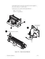
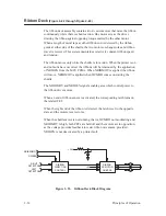
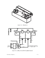
Figure 2–23. Ribbon Deck
LATCH
+5V
+27V
+36V
NSD
RH
LH
(LOW)
(HIGH)
+5V
+
+
–
–
K1
M1
K2
M2
+5V
Q1
Q2
+3.7V
+5V
END OF
RIBBON
DETECTORS
RC
RS1
R IN1
R F1
R IN2
R F2
R S2
+1V TO +5V
(VOLTAGES ARE AS INDICATED
WHEN RIBBON IS RUNNING FROM
RIGHT TO LEFT)
+17.8V
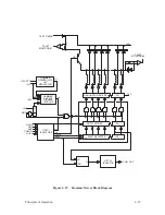
Figure 2–24. Ribbon Control PCBA Simplified Schematic
Summary of Contents for P9012
Page 1: ...P N 132305 001 Rev E P9012 Multifunction Line Printer...
Page 49: ...2 31 Principles of Operation Power Supply PCBAs 1 3 SHORT OPEN Figure 2 21 Power Supply PCBA...
Page 58: ...2 40 Principles of Operation...
Page 84: ...4 18 Troubleshooting...
Page 118: ...5 34 Alignments and Adjustments...
Page 203: ...6 85 Replacement Procedures This page intentionally left blank...
Page 214: ...6 96 Replacement Procedures...
Page 236: ...A 22 Power Paper Stacker Maintenance...
Page 246: ...D 2 Torque Table...
Page 254: ...Index 6...
Page 255: ......
Page 256: ...132305 001 Rev E...


