4–6
Troubleshooting
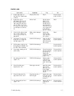
HAMMER DR PCB X *
Instruction
Indication
Yes
No
1.
Set power switch to O (OFF).
Wait 5 seconds. Set power
switch to 1 (ON).
HAMMER DR PCB X *
message.
Step 2.
Return printer to
normal operation.
2.
Press the CLEAR switch.
HAMMER DR PCB X *
message.
Step 3.
Return printer to
normal operation.
3.
Run a diagnostic self–test
(page 4–14).
HAMMER DR PCB X *
message.
Replace the
hammer driver
PCBA (page
6–74) and go to
step 4.
NOTE: X = PCBA
1, 2, or 3. #1
controls hammers
60–88; #2 controls
30–60; #3 controls
1–30.
Return printer to
normal operation.
4.
Run a diagnostic self–test
(page 4–14).
HAMMER DR PCB X *
message.
Replace one at
time until the
message
disappears: power
supply PCBA
(page 6–74) or
shuttle assembly
(page 6–18).
Return printer to
normal operation.
NOVRAM *
Instruction
Indication
Yes
No
1.
Set power switch to O (OFF).
Wait 5 seconds. Set power
switch to 1 (ON).
NOVRAM * message.
Step 2.
Return printer to
normal operation.
2.
Press the CLEAR switch.
NOVRAM * message.
Step 3.
Return printer to
normal operation.
3.
Cycle power.
NOVRAM * message.
Replace the
non–volatile RAM
chip on the DCU
PCBA.
Return printer to
normal operation.
Summary of Contents for P9012
Page 1: ...P N 132305 001 Rev E P9012 Multifunction Line Printer...
Page 49: ...2 31 Principles of Operation Power Supply PCBAs 1 3 SHORT OPEN Figure 2 21 Power Supply PCBA...
Page 58: ...2 40 Principles of Operation...
Page 84: ...4 18 Troubleshooting...
Page 118: ...5 34 Alignments and Adjustments...
Page 203: ...6 85 Replacement Procedures This page intentionally left blank...
Page 214: ...6 96 Replacement Procedures...
Page 236: ...A 22 Power Paper Stacker Maintenance...
Page 246: ...D 2 Torque Table...
Page 254: ...Index 6...
Page 255: ......
Page 256: ...132305 001 Rev E...


