Maintenance and Adjustments
4–7
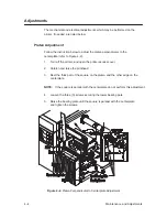
Printhead Lift Adjustment
1.
Set green head level adjust knob to lowest position.
2.
Insert a 0.5 inch wide strip of plastic 0.001 inch thick strip on each end
of the platen.
3.
Adjust the set screw until each strip releases with equal pull when the
printhead latch closed. This procedure sets the printhead lift for proper
operation with full width, standard thickness (0.007 inch) media.
Ribbon Setup Adjustment
1.
Verify that the ribbon take-up is square to the centerplate. Adjust rear
bearing plate and/or standoff if necessary.
2.
The ribbon deflector on the head mount plate should start off square.
Adjust to maintain equal tension (side to side) on the supply side to the
head.
3.
The ribbon deflector in front of the head should be parallel to the head
and not contact the tear bar.
4.
The ribbon roller behind the upper extrusion should roll freely.
5.
Print a test pattern allowing the ribbon to feed out with the paper. Verify
that no ribbon bubbling or wrinkling is evident, indicative of a concave
head.
6.
Adjust head mount deflector for minimum pull marks in ribbon.
Label Tracking
The media should track with little help from the width guide. Check for
squareness of the media roller (on the “cantilever bracket” extrusion, see
page 9–8, item 21). The outer end of this roller is controlled by the
adjustment of the hinge.
Summary of Contents for T3204 series
Page 1: ...R...
Page 2: ......
Page 3: ...R P N 136580 001 Rev C...
Page 34: ...Basic Operations 3 10...
Page 81: ...Removal and Replacement 7 23 Figure 7 24 Replacement 1 Re install printer cover see page 7 4...
Page 100: ...Spare Parts 9 2 Cover Assembly...
Page 102: ...Spare Parts 9 4 Operator Panel Assemblies...
Page 104: ...Spare Parts 9 6 Mechanism Assembly 1 5 Inch Media Supply Hub 1 of 4...
Page 106: ...Spare Parts 9 8 Mechanism Assembly 3 0 Inch Media Supply Hub 2 of 4...
Page 108: ...Spare Parts 9 10 Mechanism Assembly 3 of 4...
Page 110: ...Spare Parts 9 12 Mechanism Assembly 4 of 4...
Page 112: ...Spare Parts 9 14 Printhead Mount Assembly...
Page 114: ...Spare Parts 9 16 Linkage Assembly...
Page 116: ...Spare Parts 9 18 Bearing Plate Lower Assembly...
Page 118: ...Spare Parts 9 20 Media Sensor Assembly...
Page 124: ...Spare Parts 9 26 Rewind Option Assembly 1 of 2...
Page 126: ...Spare Parts 9 28 Rewind Option Assembly 2 of 2...
Page 128: ...Spare Parts 9 30 Final Assembly...
Page 130: ...Spare Parts 9 32 Label Guide Assembly...
Page 132: ...Spare Parts 9 34 Ribbon Saver Option 1 of 2...
Page 134: ...Spare Parts 9 36 Ribbon Saver Option 2 of 2...
Page 136: ...Spare Parts 9 38 Head Lifter Assembly...
Page 138: ...Spare Parts 9 40 Media Hub Assembly Standard...
Page 140: ...Spare Parts 9 42 Adjustable Media Hub Assembly Option...
Page 142: ...Spare Parts 9 44 Present Sensor Option...
Page 144: ...Spare Parts 9 46 Cutter and Tray Options Cutter...
Page 146: ...Spare Parts 9 48 Tray...
Page 148: ...Spare Parts 9 50...
Page 149: ......
Page 150: ...136580 001C...


