6–6
Troubleshooting
Troubleshooting Procedures
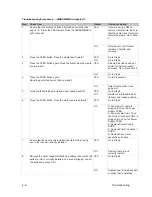
Troubleshooting Procedure 1. – NO POWER Light When Printer is Turned On
Step
Check Item
Result
Corrective Action
1.
Is power cord properly attached to the printer and to the AC
receptacle?
YES
Go to Step 2.
NO
Connect AC cord
properly.
2.
Press the FEED button. Does any mechanical movement
occur?
YES
Go to Step 5.
NO
Go to Step 3.
3.
Unplug printer. Remove the voltage selection switch/fuse hold-
er (see page 2–3). Check fuse. Is the voltage selection correct
and the fuse good?
YES
Go to Step 4.
NO
Replace fuse and/or
configure for the correct
voltage setting.
4.
Remove cover (see page 7–3). Locate the in-line fuse behind
the Printer Controller PCBA (see Figure 7–9). Is the fuse
good?
YES
Go to Step 5.
NO
Replace fuse.
5.
Remove all accessories connected to the printer (e.g., memory
cartridge, cutter, etc.). Plug the printer in and turn it ON. Is the
POWER light illuminated?
YES
Eliminate defective accessory
and replace.
NO
Go to Step 6.
6.
Unplug printer. Check the ribbon cables from Connector J2 on
the Printer Controller to Connector J1 on the Front Panel
PCBA. Is the cable properly connected and undamaged?
YES
Go to Step 7.
NO
Properly connect cable and/
or replace if necessary.
7.
Unplug printer. Unplug printhead cable from J6 on the Printer
Controller PCBA. Plug in the printer and turn it ON. Is the
POWER light illuminated?
YES
1) Replace printhead.
2) Replace printhead ribbon
cable.
NO
Go to Step 8.
8.
Unplug printer. Unplug motor assembly cable from J6 on the
Power Supply PCBA. Plug in the printer and turn it ON. Is the
POWER light come illuminated?
YES
Replace drive motor assy.
(see page 7–17).
NO
Go to Step 9.
9.
Unplug printer. Unplug the cable from J5 on the Power Supply
PCBA.
YES
Go to Step 11.
WARNING: This procedure requires measurement of
voltage. Do not cross test leads or allow
leads to touch other objects.
Plug in the printer and turn it ON. Check for approximately 8
VAC between pins 1 and 2 and approximately 10 VAC be-
tween pins 4 and 5 on the J5 connector. Are the approximate
voltages present?
NO
Go to Step 10.
Summary of Contents for T3204 series
Page 1: ...R...
Page 2: ......
Page 3: ...R P N 136580 001 Rev C...
Page 34: ...Basic Operations 3 10...
Page 81: ...Removal and Replacement 7 23 Figure 7 24 Replacement 1 Re install printer cover see page 7 4...
Page 100: ...Spare Parts 9 2 Cover Assembly...
Page 102: ...Spare Parts 9 4 Operator Panel Assemblies...
Page 104: ...Spare Parts 9 6 Mechanism Assembly 1 5 Inch Media Supply Hub 1 of 4...
Page 106: ...Spare Parts 9 8 Mechanism Assembly 3 0 Inch Media Supply Hub 2 of 4...
Page 108: ...Spare Parts 9 10 Mechanism Assembly 3 of 4...
Page 110: ...Spare Parts 9 12 Mechanism Assembly 4 of 4...
Page 112: ...Spare Parts 9 14 Printhead Mount Assembly...
Page 114: ...Spare Parts 9 16 Linkage Assembly...
Page 116: ...Spare Parts 9 18 Bearing Plate Lower Assembly...
Page 118: ...Spare Parts 9 20 Media Sensor Assembly...
Page 124: ...Spare Parts 9 26 Rewind Option Assembly 1 of 2...
Page 126: ...Spare Parts 9 28 Rewind Option Assembly 2 of 2...
Page 128: ...Spare Parts 9 30 Final Assembly...
Page 130: ...Spare Parts 9 32 Label Guide Assembly...
Page 132: ...Spare Parts 9 34 Ribbon Saver Option 1 of 2...
Page 134: ...Spare Parts 9 36 Ribbon Saver Option 2 of 2...
Page 136: ...Spare Parts 9 38 Head Lifter Assembly...
Page 138: ...Spare Parts 9 40 Media Hub Assembly Standard...
Page 140: ...Spare Parts 9 42 Adjustable Media Hub Assembly Option...
Page 142: ...Spare Parts 9 44 Present Sensor Option...
Page 144: ...Spare Parts 9 46 Cutter and Tray Options Cutter...
Page 146: ...Spare Parts 9 48 Tray...
Page 148: ...Spare Parts 9 50...
Page 149: ......
Page 150: ...136580 001C...

