background image

Prism Media Products Limited

Operation Manual

MASELEC MASTER SERIES

MEA-2 Precision Stereo Equalizer

Issue 1.2

© Prism Media Products Limited

17 January 2000

Page 8 of 20

4.1.

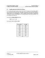
Shelf/bandwidth and boost/cut settings

The numerical bandwidth settings relate to the Q factor or sharpness of the peaking filters.
As a result of the asymmetric shape of the MEA-2 Equalizer curves it becomes difficult to
define Q factor in a meaningful way.  These settings should therefore be regarded as
indicating the relative bandwidths with 4 being the broadest and 20 the narrowest. For
more detail, see section 15.

All sections 

shelf/bandwidth

 settings:

Shelf, 4, 6, 9, 14, 20

All sections cut/boost settings (dB):

Boost (dB)

Cut (dB)

+8.0

-8.0

+6.0

-6.0

+5.0

-5.0

+4.0

-4.0

+3.0

-3.0

+2.5

-2.5

+2.0

-2.0

+1.5

-1.5

+1.0

-1.0

+0.5

-0.5

0.0

Summary of Contents for MASELEC MASTER MEA-2

Page 1: ...MASELEC MASTER SERIES MEA 2 Precision Stereo Equalizer Operation Manual Issue 1 2 17 January 2000 ...

Page 2: ...elections by Eq band 9 5 CONNECTORS 10 5 1 Input connections 10 5 2 Output connections 11 5 3 Rear panel connectors 12 6 SPECIFICATION 12 6 1 Analogue inputs 12 6 2 Analogue outputs 12 6 3 Performance specification 13 6 4 Servicing and repair 13 6 5 Mains transformer voltage selection 13 6 6 Fuse 14 6 7 Earthing 14 6 8 Physical dimensions 14 7 EQUALIZER RESPONSE CURVES 15 7 1 Range of cut boost fo...

Page 3: ... boost cut for 3300Hz shelf on HF1 18 7 9 Range of bandwidth plus shelf curve at 617Hz on HF1 19 7 10 Range of bandwidth plus shelf curve at 9000Hz on HF1 19 8 ELECTROMAGNETIC COMPATIBILITY 20 9 REFERENCES 20 Manual Revision History Issue 1 0 23 October 1997 Issue 1 1 8 January 1998 Issue 1 2 17 January 2000 Detail changes only email addr Layout Product Revision History This manual is for use with...

Page 4: ...t the end of this manual The MEA 2 employs state of the art analogue electronics and provides a perfect solution to analogue mastering needs especially used in conjunction with Prism Sound A D and D A converters Also available in the MASELEC MASTER SERIES is the MLA 2 compressor 2 SUMMARY OF MEA 2 FEATURES Operational C Four separate equalizer sections per channel C EQ in out for each channel C Al...

Page 5: ...the packaging for re use in the event that the unit should be shipped to another location or in the event that it should ever need to be returned to the manufacturer for repair or upgrade 3 2 Using the MEA 2 for the first time Connect a source of balanced audio to the input connectors on the MEA 2 Refer to section 10 for details of how to wire up interconnecting cables for the MEA 2 Connect the ou...

Page 6: ...uminated a soft green colour Switch the monitor selection to monitor the MEA 2 output The unit is now ready to use 3 3 MEA 2 product concept and capabilities The MEA 2 Precision Stereo Equalizer is designed to provide very high quality signal processing for the most demanding professional applications It has been carefully developed in conjunction with balance engineers producers and mastering eng...

Page 7: ... Each channel has four equalizer sections denoted in this manual as LF1 LF2 HF1 HF2 These are presented on the front panel in the same order as above with LF1 being on the left Each section has controls for C Response Q C Frequency C Cut Boost These parameter adjustments are interactive to a degree for example filter bandwidth is adjusted automatically while adjusting the cut boost control For fur...

Page 8: ...eaking filters As a result of the asymmetric shape of the MEA 2 Equalizer curves it becomes difficult to define Q factor in a meaningful way These settings should therefore be regarded as indicating the relative bandwidths with 4 being the broadest and 20 the narrowest For more detail see section 15 All sections shelf bandwidth settings Shelf 4 6 9 14 20 All sections cut boost settings dB Boost dB...

Page 9: ... Frequency selections by Eq band LF1 Hz LF2 Hz HF1 Hz HF2 Hz 19 21 617 665 22 24 727 787 26 29 862 937 31 34 1k 1k1 37 41 1k2 1k3 43 48 1k4 1k5 51 57 1k7 1k8 60 67 2k0 2k2 71 79 2k4 2k6 84 92 2k8 3k0 98 108 3k3 3k6 114 126 3k9 4k2 134 148 4k6 5k0 158 173 5k4 5k9 185 203 6k4 7k0 218 240 7k6 8k2 258 280 9k0 9k7 305 332 11k 12k 364 400 13k 14k 435 477 17k 19k 530 572 24k 27k ...

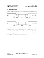
Page 10: ...erters it may be necessary to check the manufacturers polarity convention if the correct absolute phase is to be maintained However this does not affect use of the MEA 2 with either polarity convention Balanced analogue audio connections should use a good quality screened twisted pair lead Unbalanced connections must also be screened 5 1 Input connections The following diagrams illustrate correct ...

Page 11: ...ollowing diagrams illustrate correct connection for balanced and unbalanced sources Using the above method for driving unbalanced loads should provide best results It employs Ground Loop Compensation and the signal level remains unchanged compared to balanced operation Note When driving unbalanced loads with the MEA 2 the maximum output level is reduced by approximately 6dB from the nominal 28dBu ...

Page 12: ...R connector with positive and negative signal polarities on pins 2 and 3 respectively and screen on pin 1 Pins 2 3 have a high impedance path to the chassis earth Differential input impedance 27 kS pin 2 to pin 3 Single ended input impedance 27 kS pin 1 to 2 or 3 Coupling impedance to chassis 1 0 MS chassis pin 1 to 2 or 3 Common mode range 20 Vrms Note Some earlier units are 38 4 kS 6 2 Analogue ...

Page 13: ... Crosstalk less than 100 dB 20 Hz to 20 kHz Un driven input terminated 150R Harmonic distortion and noise EQ in 105dB 0 0006 997 Hz Dynamic range Measured at 32dBu EQ out 125dB EQ in 117dB 6 4 Servicing and repair There are no user serviceable parts inside this unit Repairs should only be undertaken by qualified electronics technicians or engineers 6 5 Mains transformer voltage selection The mains...

Page 14: ...320 mains inlet If this fuse is blown it should be replaced by an identical value and type 20x5mm 250V 315mAT anti surge slow 6 7 Earthing The unit has an internal link connecting the audio ground to the chassis A chassis earth stud is provided on the rear of the unit 6 8 Physical dimensions Weight 11 lb 5 kg Width 19 inch 483mm rack mountable Height 3U 77mm Depth 10 5 inches 267mm front face to r...

Page 15: ...er Issue 1 2 Prism Media Products Limited 17 January 2000 Page 15 of 20 7 EQUALIZER RESPONSE CURVES The following plots are samples of the responses of the MEA 2 equalizer All section types are represented but for brevity only a small selection of the total number of possible settings are included 7 1 Range of cut boost for 60Hz shelf on LF1 7 2 Range of cut boost for 60Hz bell curve on LF1 ...

Page 16: ...JUN 97 13 35 04 Prism Media Products Limited Operation Manual MASELEC MASTER SERIES MEA 2 Precision Stereo Equalizer Issue 1 2 Prism Media Products Limited 17 January 2000 Page 16 of 20 7 3 Range of frequency for 8dB shelf on LF1 7 4 Range of bandwidths for 8dB 530Hz bell on LF1 ...

Page 17: ...3 35 04 Prism Media Products Limited Operation Manual MASELEC MASTER SERIES MEA 2 Precision Stereo Equalizer Issue 1 2 Prism Media Products Limited 17 January 2000 Page 17 of 20 7 5 Range of bandwidth and shelf curve at 435Hz on LF1 7 6 Range of bandwidth and shelf curve at 108Hz on LF2 ...

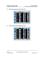
Page 18: ... JUN 97 13 35 04 Prism Media Products Limited Operation Manual MASELEC MASTER SERIES MEA 2 Precision Stereo Equalizer Issue 1 2 Prism Media Products Limited 17 January 2000 Page 18 of 20 7 7 Range of boost cut for 617Hz shelf on HF1 7 8 Range of boost cut for 3300Hz shelf on HF1 ...

Page 19: ...35 04 Prism Media Products Limited Operation Manual MASELEC MASTER SERIES MEA 2 Precision Stereo Equalizer Issue 1 2 Prism Media Products Limited 17 January 2000 Page 19 of 20 7 9 Range of bandwidth plus shelf curve at 617Hz on HF1 7 10 Range of bandwidth plus shelf curve at 9000Hz on HF1 ...

Page 20: ...elow This equipment does not include digital circuitry or generate high frequencies that could be radiated or conducted from the unit All XLR connections should use a screened twisted pair cable with the screen connected to pin 1 of the XLR connector at both ends 9 REFERENCES 1 AES17 1991 AES Standard Method for Digital Audio Engineering Measurement of Digital Audio Equipment J Audio Eng Soc Vol 3...

Reviews: