10 -
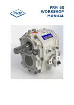
PRM 60
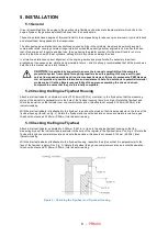
5.4 Mounting the Gearbox to the Engine
1.
Mount the drive plate to the flywheel, using an alignment mandrel if available, and bolt to the flywheel. Where
components to SAE standard are used, the outside diameter of the drive plate should be a close fit in the register
on the flywheel.
If a mandrel is not available, tighten the bolts just sufficiently to prevent free movement, assemble the gearbox to
the drive plate and rotate the engine two or three revolutions by hand to align the plate.
Tighten up two or three opposite bolts. Remove the gearbox and fully tighten all the drive plate bolts.
2.
Apply a layer of water-repellent grease to the input shaft spline and then offer the gearbox and adaptor up to the
drive plate and flywheel housing. Insert the gearbox input shaft into the centre of the drive plate (it may be
necessary to rock the shaft slightly to ensure the splines align). Press the assembly fully into position, align the
holes in the adaptor with those on the flywheel housing and tighten fully. See fastening torque chart 10.2.
5.5 Alignment to Propeller Shaft
CAUTION:
Alignment between the propeller shaft and the mating flange on the gearbox output
shaft is extremely important since excessive vibration and stress may lead to premature failure if
correct alignment is not achieved.
In the majority of boats whose hulls are rigid enough to prevent excessive flexing in heavy sea conditions, (which could
cause the engine and transmission to shift relative to the propeller shaft), it is generally considered preferable to couple
the propeller shaft direct to the gearbox output flange by means of a rigid coupling.
The two main conditions when a flexible coupling should be used are:
a) in boats whose hulls are not sufficiently rigid to prevent the flexing referred to above,
b) in cases where the engine is mounted on flexible mounts.
In both instances, the flexible coupling helps to isolate engine vibration or other movement from the propeller shaft thus
enabling correct alignment with the propeller shaft and stern tube to be maintained.
Whether a solid or flexible coupling is used, it is extremely important that the following points are carefully checked:
Summary of Contents for PRM 60
Page 1: ...PRM 60 WORKSHOP MANUAL...
Page 2: ......
Page 11: ...9 PRM 60 BASIC INSTALLATION DETAILS PRM 60 Figure 4 Intallation Details...
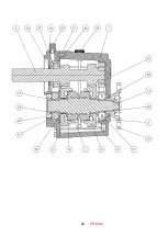
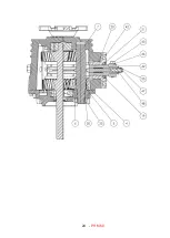
Page 23: ...21 PRM 60 13 Exploded view and Cross section Figure 5 Exploded view and cross section...
Page 24: ...22 PRM 60...
Page 25: ...23 PRM 60...
Page 26: ...24 PRM 60...
Page 28: ...26 PRM 60 NOTES...

