18 -
PRM 60
9.7.3 Idler Shaft
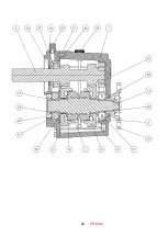
Fit the thrust washer (5) onto the idler shaft (7), fit the two needle bearings (4) onto the idler shaft (7), fit the idler gear
(6) onto the needle bearings (4)
, then fit the ‘O’ ring (55) into the shaft’s (7) groove. Then apply grase on the the ‘O’ ring
(55). Feed the idler shaft assembly through the front cover (1) bore and fit the locknut (25) and tighten to the
recommended torque (see torque chart 10.2)
9.7.4 Selector Housing Assembly
* Before proceeding with this assembly see shimming procedure 9.7.6.
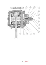
Press in oil seal (21) flush to the face of selector housing (19). Using tool number PR29418 insert into seal to expand it
whilst assembling selector control body (18) into the selector housing (19). This will displace the tool and allow the
control body (18) to slide through the seal (21)
. Fit the ‘O’ ring (20) to selector housing (19) and smear grease onto the
‘O’ ring (20), insert spring (15) and selector shoe (22) into selector housing (19).
9.7.5 Shimming (Output Bearings)
The output bearings (33) must be shimmed zero to 0.025mm preload.
This is achieved as follows:
1. Measure shaft (14) over the bearings (33).
Dimension A
2. Measure gearcase (2) bore depth to joint face.
Dimension C
3. Measure front cover (1) bore depth to joint face.
Dimension B
4. Add cover and case bore depths to give “bore face lengths”.
Dimension Y
5. Subtract bore face lengths from shaft (14) lengths over
bearings (33) to achieve shim requirement.
Dimension Y-A
6. Fit shims as required to within zero to 0.025mm preload.
Place the shims into the appropriate bore of the front cover (1) so that they are located under the bearing (33).
Locate both input and idler shaft assemblies into the respective bores. Fit the two dowels (27) and apply silicon sealant
onto the joint face. Tighten the gearcase joint to the recommended torque (see torque chart 10.2).
Fit locknut (25) to the idler shaft (7), tighten to the recommended torque (see torque chart 10.2).
Move the cone clutch (11) to the neutral position, and locate the assembled selector mechanism and secure with two
cap screws (42) to recommended tightning torque (see torque chart 10.2). Ensure the selector shoe (22) is in the grove
of the cone clutch (11), and the identification pip of the selector shoe (22) is uppermost.
Secure gear selector lever (44) to the selector body (18) using bolt (45), washer (46) and nut (47). Fit oil seal (21) to
gearcase (2) bore and oil seal (24) to the front cover (1) (see tool sheet). Assemble the output coupling (23) to the
output shaft (14).
Apply a countiniues bead of silicone sealant to the flat face of the locknut (36) and hydraulic sealant to threads of the
shaft (14). Fit locknut (36).
CAUTION:
Remember to tighten locknut (36) to the recommended torque and stake the nut into slot.
When using sealants and locking compounds all surfaces should first be cleaned by degreasing.
Summary of Contents for PRM 60
Page 1: ...PRM 60 WORKSHOP MANUAL...
Page 2: ......
Page 11: ...9 PRM 60 BASIC INSTALLATION DETAILS PRM 60 Figure 4 Intallation Details...
Page 23: ...21 PRM 60 13 Exploded view and Cross section Figure 5 Exploded view and cross section...
Page 24: ...22 PRM 60...
Page 25: ...23 PRM 60...
Page 26: ...24 PRM 60...
Page 28: ...26 PRM 60 NOTES...

