11 -
PRM 60
i) the coupling should be a tight press fit on the shaft and the keyway accurately made to the correct size, and
ii) the two halves of the coupling should be carefully aligned. This should be done by bringing the two flanges close
enough together so that a feeler gauge can be used to check the vertical and horizontal alignment.
iii) alignment should only be carried out with the boat afloat. The maximum permissable misalignment being 0.05mm.
Since the propeller shaft line is normally fixed in the boat, alignment is usually obtained by adjusting engine mount
shims on the mount themselves.
NOTE: Whenever possible, the engine and gearbox should be installed whilst the hull is afloat, otherwise there is a
danger of the hull distorting because of an insufficient support over its surface. If the engine and transmission are fitted
before the hull is in water, the installation should be very carefully re-checked for alignment after launching.
In designing PRM 60, SAE standards were adhered to as far as possible. However, other manufacturers of similar sized
transmissions have a different, but common, output coupling spigot, which is not to SAE. This spigot size has become
the industry standard and most proprietary flexible output couplings are made to suit.
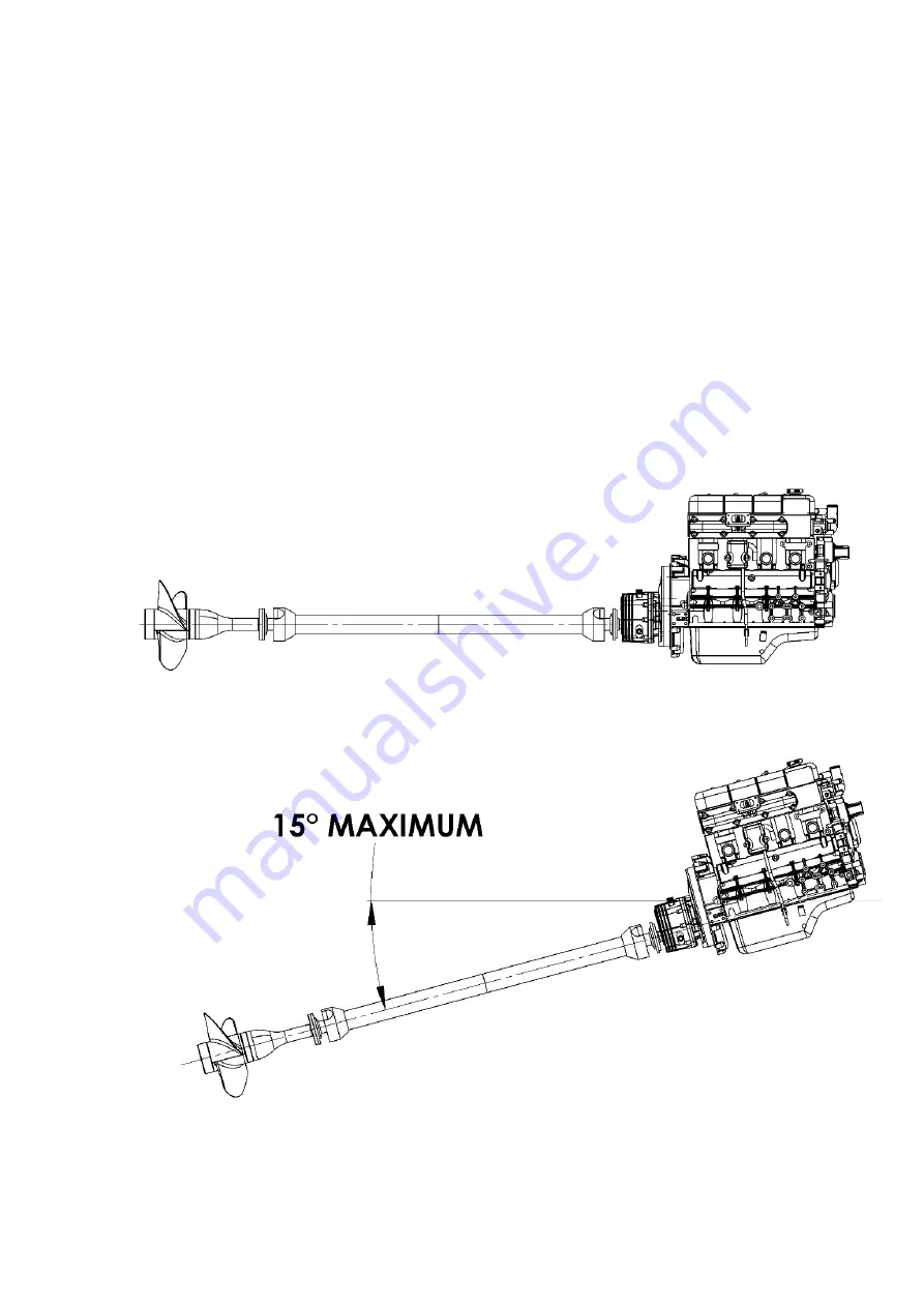
5.6 Installation angle
The transmissions should normally be installed so that the maximum fore and aft angle relative to the water line does
not exceed 15° with the boat at rest. Please consult PRM Newage Ltd. if installlation angles greater than this are
required.
Summary of Contents for PRM 60
Page 1: ...PRM 60 WORKSHOP MANUAL...
Page 2: ......
Page 11: ...9 PRM 60 BASIC INSTALLATION DETAILS PRM 60 Figure 4 Intallation Details...
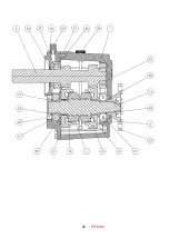
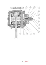
Page 23: ...21 PRM 60 13 Exploded view and Cross section Figure 5 Exploded view and cross section...
Page 24: ...22 PRM 60...
Page 25: ...23 PRM 60...
Page 26: ...24 PRM 60...
Page 28: ...26 PRM 60 NOTES...

