background image

16 


11.1


Maintenance Instruction 

The device is mostly installed in locations with dust, haze, or smoke, 

that easily pollute the lens and decrease the output brightness. These 

particles also easily pollute the light case, fans, PCBA, block the heat 

dissipation, and reduce the stability of the electronic components, so 

regular cleaning is very necessary and  important  to  keep  the 

maximum light output and increase the stability and lifetime. 
It’s  recommended  to  clean  the  lens,  the outer case,  and  the  fans 

every  2  weeks. Clean the inner  light every 4 weeks.  The cleaning 

frequency should increase when operating in severe conditions. 

Note: 

Only a qualified & authorized technician(s) is

 (are) allowed to clean 

the inner parts. Improper inner cleaning can cause serious damage to 

the  device. It’s forbidden to use corrosive chemicals to clean the 

device, pure alcohol and acetone are recommended for cleaning the 

lens. 
Clean the lens carefully and gently, don’t touch the lens with any hard 

and sharp materials. 

11.2


After Sales Service and Warranty 


One year’s warranty for the device 


The components and accessories costs are charged after the warranty 

period 


Warranty voids for the damages or injuries caused by force majeure, like, 

earthquake, typhoon, etc. 


Warranty voids for the damages or injuries caused by improper 

operation and  projection,  such  as  wrong  input  voltage,  water 

immerse, physical shock, etc. 

Summary of Contents for ECS-BEAMBOX15

Page 1: ...ECS BEAMBOX3W ECS BEAMBOX15 Thank you for purchasing our products Please read this manual before using the laser device...

Page 2: ...EAMBOX3W 7 5 2 Back Panel of BEAMBOX15 8 6 Settings Introductions 9 7 Display mode introduction 10 8 SD Card File Introduction 12 9 DMX Table 13 10 White Balance Adjustment 15 11 Safety Lock 15 11 1 M...

Page 3: ...uct Introduction New PD Series units come with diode based only laser sources and all sources have beam correction for creating a great show with analog FULL colors modulation The PD Series units can...

Page 4: ...project the beam to ammable and explosive materials Never project the beam to any easy burning items at any distance Don t use the device if there are any visible damages on housing connector panels...

Page 5: ...5 3 1 Caution Labels Warnings and other notices on the device s Aperture labels Production label...

Page 6: ...r hanging installation use a hook with a bearing level of more than 30KG and an adjustable project angle Use a safety rope with a bearing level of more than 50KG to x the device to the steady light br...

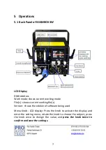
Page 7: ...ile s shows current working le s Version shows the edition of software being used Menu Knob LCD display Press the knob to activate the display and enter the setting menu rotate the knob to choose the...

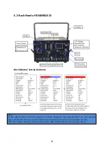
Page 8: ...on the LCD display can be freely changed to the preferable status The most important step is double click the menu knob to SAVE the preferred status when all selections settings are done The other se...

Page 9: ...the projection angle of the preset programs graphics adjustable value 10 100 Only react from the preset programs graphics no reaction under ILDA signal control Phasic setting Switch the projection di...

Page 10: ...rdingly to the laser system s color con guration when released frommanufacturer Language selection optional English or Chinese 7 Display mode introduction Audio Mode Sound mode Preset programs trigger...

Page 11: ...on is connected the ILDA computer signal control has priority and the device operates in accordance to the ILDA signal In ILDA mode a control hardware will be required the recommended one should beFB3...

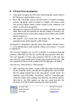
Page 12: ...play speed and play times i is the identi cation code stand for iShow and comma is used to separate it Edit only one program per line for example if a program prg1 prg contains 3 les le1 ild le2 ild a...

Page 13: ...200 255 Sound control CH4 Colors selection 0 5 O 6 16 White 6 10 ILD le color 11 16 white 17 33 Red 34 50 Green 51 67 Blue 68 84 Yellow 85 101 Purple 102 118 Cyan 119 135 White Red Green and Blue in s...

Page 14: ...irregular jumping 246 255 Irregular Jumping by sound control CH7 Zooming 0 10 None 11 87 Manual zooming 88 150 Zoom 151 200 Zoom 201 255 Circular CH8 X axis rotation 0 None 1 128 Manual 129 255 Auto C...

Page 15: ...o o CH17 Blue modulation 0 255 From the brightest to o 10 White Balance Adjustment To achieve the preferable white balance by adjusting the brightness of each color red green and blue through adjustme...

Page 16: ...operating in severe conditions Note Only a quali ed authorized technician s is are allowed to clean the inner parts Improper inner cleaning can cause serious damage to the device It s forbidden to us...

Page 17: ...5 mm Divergence full angle 1 3mrad Controls Mainboard Auto Sound SD DMX ILDA FB4 on request Scanning System DT40 40Kpps 8 30 MAX Wavelength nm R 638 G 520 B 445 Laser Power mW 650 850 1500 Modulation...

Page 18: ...SD DMX ILDA FB4 on request Scanning System DT40 40Kpps 8 30 MAX Wavelength nm R 638 G 520 B 445 Laser Power mW 4000 4000 7000 Modulation Analog W60KHz Power Supply 100 240V 50 60Hz Consumption W 290 N...

Page 19: ...ECS BEAMBOX3W ECS BEAMBOX15 Wij danken u voor het aankopen van onze producten Lees deze handleiding voordat u het laserapparaat gebruikt...

Page 20: ...EAMBOX3W 7 5 2 Back Panel of BEAMBOX15 8 6 Settings Introductions 9 7 Display mode introduction 10 8 SD Card File Introduction 12 9 DMX Table 13 10 White Balance Adjustment 15 11 Safety Lock 15 11 1 M...

Page 21: ...soires zoals ILDA kabel besturingssystemen enz 2 Product Introduction New PD Series units come with diode based only laser sources and all sources have beam correction for creating a great show with a...

Page 22: ...project the beam to ammable and explosive materials Never project the beam to any easy burning items at any distance Don t use the device if there are any visible damages on housing connector panels...

Page 23: ...5 3 1 Caution Labels Warnings and other notices on the device s Aperture labels Production label...

Page 24: ...r hanging installation use a hook with a bearing level of more than 30KG and an adjustable project angle Use a safety rope with a bearing level of more than 50KG to x the device to the steady light br...

Page 25: ...ile s shows current working le s Version shows the edition of software being used Menu Knob LCD display Press the knob to activate the display and enter the setting menu rotate the knob to choose the...

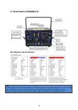
Page 26: ...on the LCD display can be freely changed to the preferable status The most important step is double click the menu knob to SAVE the preferred status when all selections settings are done The other se...

Page 27: ...the projection angle of the preset programs graphics adjustable value 10 100 Only react from the preset programs graphics no reaction under ILDA signal control Phasic setting Switch the projection di...

Page 28: ...rdingly to the laser system s color con guration when released frommanufacturer Language selection optional English or Chinese 7 Display mode introduction Audio Mode Sound mode Preset programs trigger...

Page 29: ...on is connected the ILDA computer signal control has priority and the device operates in accordance to the ILDA signal In ILDA mode a control hardware will be required the recommended one should beFB3...

Page 30: ...play speed and play times i is the identi cation code stand for iShow and comma is used to separate it Edit only one program per line for example if a program prg1 prg contains 3 les le1 ild le2 ild a...

Page 31: ...200 255 Sound control CH4 Colors selection 0 5 O 6 16 White 6 10 ILD le color 11 16 white 17 33 Red 34 50 Green 51 67 Blue 68 84 Yellow 85 101 Purple 102 118 Cyan 119 135 White Red Green and Blue in s...

Page 32: ...irregular jumping 246 255 Irregular Jumping by sound control CH7 Zooming 0 10 None 11 87 Manual zooming 88 150 Zoom 151 200 Zoom 201 255 Circular CH8 X axis rotation 0 None 1 128 Manual 129 255 Auto C...

Page 33: ...o o CH17 Blue modulation 0 255 From the brightest to o 10 White Balance Adjustment To achieve the preferable white balance by adjusting the brightness of each color red green and blue through adjustme...

Page 34: ...operating in severe conditions Note Only a quali ed authorized technician s is are allowed to clean the inner parts Improper inner cleaning can cause serious damage to the device It s forbidden to us...

Page 35: ...5 mm Divergence full angle 1 3mrad Controls Mainboard Auto Sound SD DMX ILDA FB4 on request Scanning System DT40 40Kpps 8 30 MAX Wavelength nm R 638 G 520 B 445 Laser Power mW 650 850 1500 Modulation...

Page 36: ...SD DMX ILDA FB4 on request Scanning System DT40 40Kpps 8 30 MAX Wavelength nm R 638 G 520 B 445 Laser Power mW 4000 4000 7000 Modulation Analog W60KHz Power Supply 100 240V 50 60Hz Consumption W 290 N...

Page 37: ...ECS BEAMBOX3W ECS BEAMBOX15 Merci d avoir achet nos produits Lisez ce manuel avant d utiliser l appareil laser...

Page 38: ...EAMBOX3W 7 5 2 Back Panel of BEAMBOX15 8 6 Settings Introductions 9 7 Display mode introduction 10 8 SD Card File Introduction 12 9 DMX Table 13 10 White Balance Adjustment 15 11 Safety Lock 15 11 1 M...

Page 39: ...s tels que le c ble ILDA les syst mes de contr le etc 2 Product Introduction New PD Series units come with diode based only laser sources and all sources have beam correction for creating a great sho...

Page 40: ...project the beam to ammable and explosive materials Never project the beam to any easy burning items at any distance Don t use the device if there are any visible damages on housing connector panels...

Page 41: ...5 3 1 Caution Labels Warnings and other notices on the device s Aperture labels Production label...

Page 42: ...r hanging installation use a hook with a bearing level of more than 30KG and an adjustable project angle Use a safety rope with a bearing level of more than 50KG to x the device to the steady light br...

Page 43: ...ile s shows current working le s Version shows the edition of software being used Menu Knob LCD display Press the knob to activate the display and enter the setting menu rotate the knob to choose the...

Page 44: ...on the LCD display can be freely changed to the preferable status The most important step is double click the menu knob to SAVE the preferred status when all selections settings are done The other se...

Page 45: ...the projection angle of the preset programs graphics adjustable value 10 100 Only react from the preset programs graphics no reaction under ILDA signal control Phasic setting Switch the projection di...

Page 46: ...rdingly to the laser system s color con guration when released frommanufacturer Language selection optional English or Chinese 7 Display mode introduction Audio Mode Sound mode Preset programs trigger...

Page 47: ...on is connected the ILDA computer signal control has priority and the device operates in accordance to the ILDA signal In ILDA mode a control hardware will be required the recommended one should beFB3...

Page 48: ...play speed and play times i is the identi cation code stand for iShow and comma is used to separate it Edit only one program per line for example if a program prg1 prg contains 3 les le1 ild le2 ild a...

Page 49: ...200 255 Sound control CH4 Colors selection 0 5 O 6 16 White 6 10 ILD le color 11 16 white 17 33 Red 34 50 Green 51 67 Blue 68 84 Yellow 85 101 Purple 102 118 Cyan 119 135 White Red Green and Blue in s...

Page 50: ...irregular jumping 246 255 Irregular Jumping by sound control CH7 Zooming 0 10 None 11 87 Manual zooming 88 150 Zoom 151 200 Zoom 201 255 Circular CH8 X axis rotation 0 None 1 128 Manual 129 255 Auto C...

Page 51: ...o o CH17 Blue modulation 0 255 From the brightest to o 10 White Balance Adjustment To achieve the preferable white balance by adjusting the brightness of each color red green and blue through adjustme...

Page 52: ...operating in severe conditions Note Only a quali ed authorized technician s is are allowed to clean the inner parts Improper inner cleaning can cause serious damage to the device It s forbidden to us...

Page 53: ...5 mm Divergence full angle 1 3mrad Controls Mainboard Auto Sound SD DMX ILDA FB4 on request Scanning System DT40 40Kpps 8 30 MAX Wavelength nm R 638 G 520 B 445 Laser Power mW 650 850 1500 Modulation...

Page 54: ...SD DMX ILDA FB4 on request Scanning System DT40 40Kpps 8 30 MAX Wavelength nm R 638 G 520 B 445 Laser Power mW 4000 4000 7000 Modulation Analog W60KHz Power Supply 100 240V 50 60Hz Consumption W 290 N...

Reviews: