background image

WWW.PROCUTUSA.COM 

PG /


29

Now that you have adjusted for depth, tighten the forward lock lever (over the tool arms).  This lever must 
be tight to minimize vibration.  

For safety, it is advised at this time that you turn the motor off.  Place the 

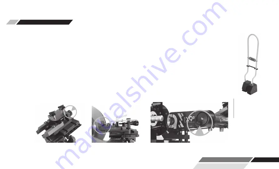
chip deflector around the rotor and over the cutting tips.  Grooves in the chip deflector will fit snugly over 
the cutting tip screw heads when installed correctly.  There are currently three types of chip deflector.  The 
first, the 50-703 standard version, is used in most smaller vented rotor applications.  The second, the 50-
754, has double thick blocks and a lock clip to increase pressure on the rotor.  The 50-754 chip deflector 
works well on the thin solid rear rotors.  The third, the 50-744, has thicker wire and a stronger spring for 
larger vented rotors on larger cars and trucks.

Once cut depth is set, tool arms are locked down, chip deflector is secure, and draw bar tightness is double 
checked, you may turn the motor back on. Press the feed engagement knob to engage the automatic feed.  
Provided that you previously set the shut-off cam correctly, the lathe will shut off when the cut is com-
plete.  The cut will take two to four minutes depending on the size of the rotor.

Step 4: MAKE THE CUT 

(4 Minutes) CONTINUED

6.

7.

MACHINING ROTORS


Pictured above is the 
50-754, which has 
double thick blocks and 
a lock clip to increase 
pressure on solid thin 
rear rotors. 

Turn the dials clockwise to advance the 
cutting tip depth.  Each click of the dial 
indicates .001”.

The chip deflectors ride over the cutting 
arms as shown above.  The chip deflec-
tor should be used every time.

Move the cutting head by turning the knob 
shown above, clockwise for away from 
the rotor, counter-clockwise for towards 
the rotor.

Summary of Contents for X9D

Page 1: ......

Page 2: ......

Page 3: ......

Page 4: ......

Page 5: ...P 800 543 6618 F 603 298 8404 info procutusa com www procutusa com TECHNICAL MANUAL DC ROTOR MATCHING SYSTEM...

Page 6: ...of Standard Accessories Acceptance from Carrier Safety Information Operations Procedures Vehicle Preparation Lathe Preparation Helpful Hints for Rotor Cutting Machining Rotors 9 10 11 12 13 14 14 18 1...

Page 7: ...We have worked with learned from and solved problems for people at all levels of the brake repair business from the largest auto manufacturers and national service chains to one bay one man operation...

Page 8: ...me to read this owner s manual carefully and store this manual in a safe place for future reference Our job is not done until you feel your technician team is trained properly and received all the inf...

Page 9: ...ment is defective subject to the limitations of this warranty we will replace it at no charge for labor Pro Cut International warrants any such work done against defects in materials or workmanship fo...

Page 10: ...1 2 3 4 5 7 8 9 11 13 12 14 6 10 PG 10 800 543 6618 Lathe Overview...

Page 11: ...ob 2 Motor 3 Emergency Stop 4 Spindle Start Stop 5 Adjustment Solenoid 6 Belt Cover 7 LED Task Lamp COMPONENTS 8 Performance Plus Cutting Head 9 Microswitch 10 Disc Lock Lever 11 Feed Clutch Not Shown...

Page 12: ...00mm Maximum width of friction surface 3 62 92mm Maximum thickness 2 00 50 8mm Variable Spindle Speed Feed per Spindle Revolution 005 Motor 1 0 HP DC up to 1kW Lathe Weight 110 lbs 50 kg Lathe Shippin...

Page 13: ...Cone Extension 1 30 791 Spacer Ring 1 50 703 Chip Deflector 1 50 778 Cutting Tips 1 50 744 Large Chip Deflector 1 50 376 Way Oil 1 50 754 Chip Deflector 1 37 1900 Safety Glasses IMAGES NOT TO SCALE S...

Page 14: ...the brake lathe Its purpose aside from proper maintenance and operations is to promote safety through the use of accepted practice READ AND UNDERSTAND THE SAFETY AND OPERATING INSTRUCTIONS COMPLETELY...

Page 15: ...malfunction or breakdown grounding provides a path of least resistance for electric current to reduce the risk of electric shock The lathe is equipped with an electric cord having an equipment groundi...

Page 16: ...not provide the degree of protection necessary RESPIRATORY SAFETY If the operation or area is dusty a face or dust mask should be used PERSONAL PROTECTION Before operating the machine remove tie ring...

Page 17: ...chine on CHECK DAMAGED PARTS Before further use of the lathe a guard or other part that is damaged should be carefully checked to determine if it will operate properly and perform its intended functio...

Page 18: ...turned off and the spindle brought to a complete stop before the operator departs In addition if the operation is complete the operator should clean the machine and work area NEVER CLEAN THE MACHINE...

Page 19: ...locking axles you may need to reduce the speed to 50 to stay below lock up rpm No guarantee can be made for inserts not purchased from Pro Cut as insert corner radius relief angle material composition...

Page 20: ...ate job possible 3 Remove the wheels Remove the brake calipers and suspend them out of the way of moving parts such as half shafts and CV joints using the yellow S hooks provided pn 37 034 Be sure to...

Page 21: ...the rear of the hub begin on the driver s side When you flip the lathe to machine the opposite side of the vehicle FIG 2 no inboard outboard cutting head adjustments are required since they were made...

Page 22: ...when to rotate tips monitor rotor finish If the rotor finish begins to look inconsistent or feels rough to the touch tips should be rotated Tips that are chipped or cracked should never be used Be sur...

Page 23: ...the vehicle and stabilize the opposing rotor so it does not rock Be sure that the Emergency Brake is released If ambient temperature is well below freezing and the vehicle is all wheel drive warm veh...

Page 24: ...rger passenger cars and smaller trucks use the 50 693 adapter For most trucks and vans use the larger adapter 50 681 or the 50 694 See the adapter search on the Pro Cut website or SuperTech app for mo...

Page 25: ...o thread into the adapter securely connecting the lathe to the vehicle NOTE It is very important that the machine be mounted smoothly on the adapter without pry ing or forcing Take the time to align t...

Page 26: ...feedback on the compensated status of the lathe When the machine is done adjusting a displayed value on the DRO will give feedback on the status of the lathe For example a measurement of 0 0015 38 mi...

Page 27: ...rolley Run the adjustment procedure and the machine will should adjust for run out If ALERT appears repeatedly there is most often a problem with the vehicle You should dismount the machine and check...

Page 28: ...de starting point of the cut Be careful not to crank the cutting arms into the hat of the rotor Damage caused by advancing the cutting arm into the hat of the rotor is not covered by warranty When you...

Page 29: ...g for larger vented rotors on larger cars and trucks Once cut depth is set tool arms are locked down chip deflector is secure and draw bar tightness is double checked you may turn the motor back on Pr...

Page 30: ...the Pro Cut Brake Spec Guide provided or other reliable certified source When you have finished your measurements be sure to clear the hub caliper bracket and speed sensors of any brake chips dust or...

Page 31: ...ntil you advance the cutting head slightly The cutting arms will also still be advanced in from the last cut so be sure to loosen the forward lock lever and spread the tool arms before feeding the hea...

Page 32: ...ed of chips and dust Special care should be used in making sure that ABS sensors are free of debris Reassemble the brakes and wheels to the manufacturer s specifications VEHICLE REASSEMBLY Be sure to...

Page 33: ...ting in place If chips do rust in place they can often be dislodged by poking a needle through the hole Clean the slide plate and tool holder plate taking special care that there are not chips or dirt...

Page 34: ...n during machining is the key to high quality surface finish It is critical that all con tact points between the rotor and the lathe are secure specifically the connections between lathe and adapter t...

Page 35: ...TIPS On each brake job the technician must center the cutting head Once the head is centered it is vital that the technician tighten the cutting head lateral lock lever securely Failure to do this ma...

Page 36: ...PG 36 800 543 6618 MACHINING MODE FROM HOME SCREEN EMERGENCY STOP Spindle Motor ON OFF Spindle Speed Control 40 100 Power LRO Compensation Button Lathe Control Panel Function Indicator Lights...

Page 37: ...nds to enter set up mode Rotate to scroll through options and toggle between choices within an option Short press to select option or drill down to another level Long press to accept changes Available...

Page 38: ...tatistics Mode Short Press 3 seconds to enter Statistics mode Rotate right to scroll through options Available Statistics LRO Compensations rotors machined Life Average Compensation Time Last 5 Compen...

Page 39: ...debris Grasping the slide plate on the side opposite of the slide rail wiggle it back and forth at the same time push on the side where the rail is located Slide Plate Resistance Adjustment 1 2 3 4 5...

Page 40: ...paired or replaced before rotors are match machined It is also important that the machine be supported by the trolley during adjustment LATERAL Run out ADJUSTMENT CALIBRATION PROCEDURE The Pro Cut PFM...

Page 41: ...WWW PROCUTUSA COM PG 41...

Page 42: ...DAPTER LARGE Fits larger 5 lug cars and smaller SUVs and trucks such as Toyota Camry most BMW models and Chevy Equinox ADAPTER PACKAGES 6 LIGHT DUTY 6 LUG ADAPTER 6 lug adapter fits newer Colorado Can...

Page 43: ...may interfere with the 50 691 adapter 3 4 TON TRUCK ADAPTER COMMON Fits most 3 4 ton single wheel trucks front and rear DUAL WHEEL TRUCK ADAPTER Fits 1 ton Ford Dodge and Chevy trucks and vans with d...

Page 44: ...6 50 2136 1 7 50 1831 1 8 50 566 1 9 50 570 1 10 50 565 1 11 37 1808 1 12 50 567 1 13 50 2217 1 14 37 117 1 15 35 251 1 16 50 2220 1 17 50 1400 1 18 50 1804 1 20 50 145 1 21 50 1330 1 22 50 2211 1 23...

Page 45: ...1 7 50 1831 1 8 50 566 1 9 50 570 1 10 50 565 1 11 37 1808 1 12 50 567 1 13 50 2217 1 14 37 117 1 15 35 251 1 16 50 2220 1 17 50 1400 1 18 50 1804 1 20 50 1650 1 21 50 1330 1 22 50 2211 1 23 50 1142...

Page 46: ...0 2074 2 17 50 2075 2 18 37 485 2 19 50 1032 2 20 37 721 2 21 35 239 6 22 37 498 4 23 36 001B 8 24 50 868 BK 2 25 50 2077 Y 1 26 50 2078 Y 1 27 50 1061 1 28 50 1062 2 29 37 1065 1 30 35 307 2 31 35 81...

Page 47: ...0 2074 2 17 50 2075 2 18 37 485 2 19 50 1032 2 20 37 721 2 21 35 239 6 22 37 498 4 23 36 001B 8 24 50 868 2 25 50 1456 1 26 50 2078 1 27 50 1061 1 28 50 1062 2 29 37 1065 1 30 35 307 2 31 35 815 2 32...

Page 48: ...T NUMBER QTY 1 50 1331 1 2 37 1333 2 3 50 1332 1 4 50 1333 1 5 50 1334 1 6 50 1335 1 7 50 1336 1 8 50 1339 2 9 50 053 1 10 50 252 1 11 37 1331 1 12 50 1343 1 13 35 1331 2 14 35 1335 2 15 37 1332 2 16...

Page 49: ...1 4 3 8 7 5 2 6 11 9 10 ITEM NO PART NUMBER QTY 1 50 139 1 2 50 1247 1 3 50 489 1 4 35 237 2 5 50 1340 1 6 50 1824 1 7 35 934 5 8 36 019 5 9 50 1341 1 10 35 270 2 11 50 1671 1 WWW PROCUTUSA COM PG 49...

Page 50: ...0 1651 1 2 37 056 2 3 50 016 1 4 50 1668 1 5 37 057 2 6 35 927 4 7 50 018 1 8 35 926 1 9 50 021 1 10 50 1342 1 11 50 1667 1 12 50 1657 2 13 35 951 2 14 50 1208 3 15 37 1250 3 16 37 077 4 17 50 1665 1...

Page 51: ...2 3 ITEM NO PART NUMBER DESCRIPTION QTY 1 50 2247 X9 Lathe Guard Weldment 1 2 37 1730 B18 22M Plain washer 10 mm Wide Steel Bright Zinc 1 3 35 275 Hexagon head screw ISO 4017 M10 x 20 1 WWW PROCUTUSA...

Page 52: ...ITEM NO PART NUMBER QTY 1 50 2201 1 2 50 1565 1 3 37 1854 1 4 50 1871 1 5 37 1849 1 6 50 1843 1 7 37 1858 1 8 50 2246 1 9 37 003 4 10 36 002 4 11 37 425 1 12 37 426 1 13 35 280 5 14 35 838 3 15 35 80...

Page 53: ...WWW PROCUTUSA COM PG 53...

Page 54: ...long to com plete too many revolutions Message is cleared by pressing the motor stop start button or rotating or pressing the motor speed knob If you get this message repeatedly there may be issues w...

Page 55: ...is between 100 and 110 After 110 compenstations this message will be automatically suppressed None Continue use as normal Call 800 543 6618 to inquire about the current free gift Motor draws excessive...

Page 56: ...a temperature fault has occurred Current temp is below the fault threshold but still too warm to restart spindle The message text displays current temperature in deg C Wait for the displayed temperatu...

Page 57: ...provided that the lathe is equipped with a thickness measure ment electronics optional Note the leading character is the lower bar of the 1st character None this message is displayed if electronic me...

Page 58: ...ary encoders are report ing faults Power cycle lathe and or replace Tcm Cut Detected cut Lathe is equipped with a disc thickness mea suring and cutting sounds have been detected None Informational ale...

Page 59: ...WWW PROCUTUSA COM PG 59 NOTES...

Page 60: ...PG 60 800 543 6618 MAINTENANCE SCHEDULE DATE DRO READINGS HOURS TOTAL DISCS TOTAL DRUMS MONTH DAY YEAR NOTES...

Page 61: ...WWW PROCUTUSA COM PG 61 MAINTENANCE SCHEDULE DATE DRO READINGS HOURS TOTAL DISCS TOTAL DRUMS MONTH DAY YEAR NOTES...

Page 62: ...PG 62 800 543 6618...

Page 63: ...WWW PROCUTUSA COM PG 63...

Page 64: ...0 Technology Drive 4 West Lebanon NH 03784 50 763 PRINTED WITH PRIDE IN THE U S A PRO CUT INTERNATIONAL LLC Global inquiries please see www procutusa com P 800 543 6618 603 298 5200 F 603 298 8404 E i...

Reviews: