background image

InsTallaTIon

10 

EmpyrE ElItE Xt InstallatIOn and OpEratIOn manual

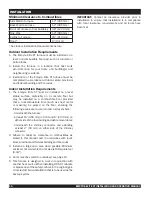
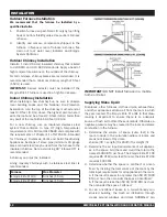
minimum Clearance to Combustibles

Side Wall to Furnace

12” (305 mm)

Back Wall to Furnace

12” (305 mm)

Front of Furnace to Combustibles

48” (1220 mm)

Flue Pipe

12” (305 mm)

Ceiling to Furnace

24” (610 mm)

Floor*

0” (0 mm)

*See Indoor Installation Requirements below.

Outdoor Installation requirements

1.  The Empyre Elite XT furnace must be installed on a 

level, noncombustible floor pad, such as concrete or 

patio blocks.

2. Install the furnace in a location that best suits 

wind direction for your home and building(s) and 

neighbouring residents.

3.  Installation of the Empyre Elite XT furnace must be 

completed in accordance with local, state, provincial 

and federal building and fire codes.

Indoor Installation requirements

1. The Empyre Elite XT must be installed on a level 

stable  surface,  preferably  on  a  concrete  floor  but 

may  be  installed  on  a  combustible  floor  provided 

that a noncombustible liner (such as sheet metal 

or  masonry)  be  placed  on  the  floor,  ensuring  the 

following areas are covered to catch stray embers:

  -  Underneath the furnace; 

  - At least 16” (406 mm) in front and 8” (203 mm) on 

either side of the fuel loading and ash removal doors; 

 - Underneath the chimney connector and extending 

at least 2” (50 mm) on either side of the chimney 

connector.

2. Adhere to minimum clearance to combustibles as 

stated in this manual and in accordance with local, 

state, provincial and federal building and fire codes. 

3.  Install in a large open area when possible. Minimum 

enclosed, not well vented, room size is 100 square feet 

(9.3m

2

).

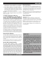
4.  Room must be vented to outside air, see page 12.

5.  This  furnace  is  designed  to  work  in  conjunction  with 

another heat source. When installing, DO NOT relocate 

or bypass any of the safety controls in the original (gas, 

oil or electric) boiler installation that is to be used as the 

backup system.

ImpOrtant:

 Contact an insurance provider prior to 

installation to ensure that installation is in compliance 

with local insurance requirements and all terms have 

been met.

Summary of Contents for Empyre Elite XT

Page 1: ...Installation and Operation Instructions Empyre Elite XT Model 100 and 200...

Page 2: ......

Page 3: ...tion Dimensions 11 Trench for Underground Pipes 11 Outdoor Furnace Installation 12 Outdoor Chimney Installation 12 Indoor Chimney Installation 12 Supplying Make Up Air 12 Low Water Temperature Protect...

Page 4: ...During Heating Season 20 End of Heating Season 21 Reference 22 27 Operating the Digital Temperature Switch DTS 22 Hot Water Wood Furnace Wiring Diagram 23 How to Correct a Sticking Flapper 24 Furnace...

Page 5: ...e Empyre Elite XT Works The Empyre Elite XT uses a process called wood gasification to produce highly efficient combustion in the furnace s dual burn chambers 1 Wood in the firebox burns from the bott...

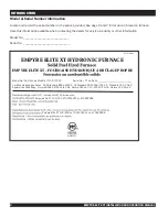
Page 6: ..._________ Serial No _______________________________ EMPYRE ELITE XT HYDRONIC FURNACE 15 Empyre Elite XT 100 200 702112231 or 70626288 Empyre Elite XT 100 200 no 702112231 ou no 70626288 817978R00 Mode...

Page 7: ...running mode timer is then locked out 2 After loading CLOSE and LATCH door firmly and move LEVER to the right DO NOT operate with loading door open ASH REMOVAL DOOR ALWAYS OPEN SLOWLY 1 ALWAYS switch...

Page 8: ...ally hazardous situation that if not avoided MAY result in minor or moderate injury if proper practices are not taken or serves as a reminder to follow appropriate safety practices Safety Decals Pleas...

Page 9: ...PA 211 and NFPA90B Chimney must be a listed UL 103 HT or ULC S629 residential all fuel type or tile lined masonry Flue connector pipe must be made of a minimum 24 NSG black steel Special precautions a...

Page 10: ...or Panel 13 Secondary Burn Chamber 13 A Brick Configuration No Description 13 B Insulation Board Configuration 14 Ash Tray 15 Smoke Deflector Angle 16 Latch Catch Locking Bolt Front Rear Door 17 Latch...

Page 11: ...39 Electric Element Ports 40 Flue Cleaning Tool 41 Drain 42 Rear Lower Cover No Description 43 Right Side Panel 44 Supply Port 1 Elite XT 100 1 1 4 Elite XT 200 45 Flue Clean Out Cover 46 Probe Shiel...

Page 12: ...rovided that a noncombustible liner such as sheet metal or masonry be placed on the floor ensuring the following areas are covered to catch stray embers Underneath the furnace At least 16 406 mm in fr...

Page 13: ...to determine the line size necessary to meet the demands of your specific application 4 Identify each water line clearly in order to correctly locate the supply and return lines 5 Lay down 14 2 under...

Page 14: ...Sections of stove pipe minimum 24 gauge black or blued steel may be used from the furnace to the insulated chimney Note avoid using 90 Elbows 45 is recommended A chimney cap must be installed Lining m...

Page 15: ...ESO and Valve Operates The Empyre System Optimizer provides a constant circulation of water through the boiler and the Danfoss VTC tempering valve Water is drawn off the low loss header by the buildin...

Page 16: ...Closely Spaced Tees See Note Empyre Elite XT Figure 2 Connect to Existing Boiler Pump Boiler Return Plate Exchanger Pump Boiler Supply Existing Boiler Return from System Pump ESO Figure 3 Empyre Elit...

Page 17: ...arm as low as possible Side Arm Installation Figure 1 To domestic heating system Hot water in from Pro Series furnace To top of hot water tank From bottom of hot water tank Figure 2 PUMP BALL VALVE TH...

Page 18: ...through vent opening Figure 1 9 Check water level when water temperature is 170 F 77 C and add water until level indicator shows full Maintaining Proper Water Level When the water level is low the Em...

Page 19: ...wood when possible When using the recommended seasoned wood where the moisture content is between 19 and 25 the diameter of the wood is not that important Scenario 1 is also created when stirring a h...

Page 20: ...out ash tray 4 Reach the ash rake to the back of the chamber and pull ash forward into the ash tray Do not scrape all of the ash into the ash tray It is recommended to leave 1 2 2 5 5 1 cm of ash cov...

Page 21: ...nace WILL NOT operate To maintain optimal performance 1 Do not leave loading door open for extended periods of time especially when the fire is very hot 2 Do not force the loading door open beyond the...

Page 22: ...er flues weekly A buildup in the flues and chimney will cause a poor draft and reduce efficiency 6 Check and clean the air passages in the upper loading door frame several times during the heating sea...

Page 23: ...treatment is in the system In the event that there has been water loss through the season additional water treatment will need to be added Follow the treatment ratio on the bottle for additional gallo...

Page 24: ...ircuit probe error Open probe error DTS Technical Data Accuracy 1 Output 16 Amp 1HP 240 Vac SPDT relay Supply voltage 115 Vac 10 Display 3 digit red DTS Programming Press SET SP text will appear on th...

Page 25: ...range 1 White Orange Yellow Blue Blue Blue Yellow Purple White Red Orange Ground 110 volts AC 60Hz Black power line White neutral line NO NC 2 CAUTION DO NOT CONNECT THE ELECTRICAL COMPONENTS OF THIS...

Page 26: ...ist 1 Check if furnace is being operated properly 2 Remove flapper unit check to ensure the flap seals in the closed position clean and oil How to Remove and Reinstall 1 Disconnect power 2 Remove blow...

Page 27: ...15 cm 6 in 15 cm Log Length 24 in 61 cm 25 in 64 cm Log Diameter 6 in 15 cm 6 in 15 cm Furnace Weight excluding pallet 1 050 lb 476 kg 1 635 lb 742 kg Water Capacity 60 US Gal 227 L 112 US Gal 424 L N...

Page 28: ...569 9 61 81 335 2 13 20 852 5 33 56 1484 5 58 45 Elite 100 Unit Dimensions 3 1 4 1 2 Not shown 0 817753 Revisions DESCRIPTION ECO Production Release 2535 REV Figure 2 Brick Layout Figure 3 Refractory...

Page 29: ...Front Burn Chamber Elite 200 1 3 1 2 4 Elite 200 Refractory Layout ITEM NO PART NO DESCRIPTION QTY 1 816951 Insulation Fibre Board Side Burn Chamber Elite 200 6 2 816952 Insulation Fibre Board Bottom...

Page 30: ...s air passage in the firebox floor is blocked by charcoal ash Using the ash rake always stir the firebox charcoal ash into the lower ash chamber before adding wood Limit the charcoal ash buildup and l...

Page 31: ......

Page 32: ...Registration and a copy of the original bill invoice must be forwarded to Pro Fab within thirty 30 days of the date of purchase to validate the warranty Issue Date February 2013 Part No 817969R01 Prin...

Reviews: