background image

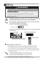
Under 6.0mm(0.24in)

Over 

φ

3.2mm(0.13in)

• Wherever possible, use thick wires (max.2mm

2

) for power terminals, and twist the

wire ends before attaching the ring terminals.

• Be sure to use the following size ring terminals.

*1

• To avoid a short caused by loose ring terminals, be sure to use ring terminals with an

insulating sleeve.

WARNINGS

6

Wiring

To avoid an electric shock, when connecting the FP unit's power cord terminals to
the power terminal block, confirm that the power supply is completely turned OFF,
via a breaker, or similar unit.

FP2500-T42-24V/FP2600-T42-24V units are designed to use only DC24V input.
Any other power level can damage both the FP and the power supply.

Since there is no power switch on the FP unit, be sure to attach a breaker-type
switch to its power cord.

*1

Suggested Ring Terminal : equivalent to V2-MS3 (made by JST)

• When the FG terminal is connected, be sure the wire is grounded. Not

grounding the FP unit will result in excess noise and vibration.

Rear of FP

Ring Terminals

*1

Power Input Terminal Block

+    -   FG

+    -    FG

„

„

„

„

„

Connecting the AC Power Cord

When connecting the power cord, be sure to follow the procedures given below.

1. Confirm that the FP unit's Power Cord is unplugged from the power supply.

2. Use a screwdriver to remove the Power Input Terminal Block's clear plastic cover.

3. Unscrew the screws from the middle three (3) terminals, align the Ring Terminals

and reattach the screws.

4. Replace the Power Input Terminal Block's clear plastic cover.

Confirm that the ring terminal wires are connected correctly.

• The torque required to tighten these screws is 0.5 to 0.6 N•m.

Summary of Contents for FP2500-T42-24V

Page 1: ...d out and touches the panel a potentially dangerous machine operation error can occur Therefore do not use FP unit touch screen switches for the control of equipment safety mechanisms such as Emergency Stop switches etc that protect humans from injury and equipment from damage If your FP unit s backlight suddenly turns OFF use the following steps to determine if the backlight is actually burned ou...

Page 2: ... leading to a mal function To prevent excessive heat from building up inside the unit do not install the FP where its ventilation holes may be blocked Also do not install or store the FP near high temperatureequipment Do not install or store the FP where direct sunlight or high levels of dust exist Since the FP is a precision instrument do not install or store it where either strong shocks or exce...

Page 3: ...manyadjacentstructuresormachineparts Iftheseconditionsarenotmet theheatgeneratedbytheFPunit sinternalcomponentsmaycausethe unit to fail to meet UL standard UL1604 Conditions of Acceptability and Handling Cautions 1 Power inputandoutput I O wiringmustbeinaccordancewithClassI Division2wiringmethods Article 501 4 b of the National Electrical Code NFPA 70 within the United States and in accordance wit...

Page 4: ...r should you find anything damaged or missing please contact your local FP distributor immediately Package Contents FP unit CD ROM 1 FP2500 T42 24V FP2600 T42 24V FP 2500 FP 2600 Series User Manual Touch Panel Programs for MS DOS Installation Gasket 1 Installation Brackets 4 set Installation Guide 1 USB Cable Strap 1 this manual Options Cables Touch Panel Driver Software Maintenance Parts Installa...

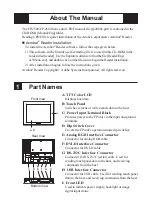
Page 5: ...receiving commands from the host I Front LED Used to indicate power supply backlight or image signal input status Front View Rear View A B I Bottom View C D E F G H The FP 2500 FP 2600 Series unit s PDF manual file fp2000e pdf is contained in the CD ROM s Manual Eng folder Reading a PDF file requires installation of the Adobe Corporation s Acrobat Reader Acrobat Reader Installation To install the ...

Page 6: ...nit mm in Front View 301 11 85 227 8 94 243 9 57 317 12 48 58 2 28 Top View 8 0 31 Side View FP2500 T42 24V FP2600 T42 24V Unit mm in Front View 301 11 85 227 8 94 243 9 57 317 12 48 58 2 28 Top View 8 0 31 Side View ...

Page 7: ...panel data transmission Used to set the touch panel data input command control method to either USB or RS 232C ON USB OFF RS 232C Default setting 1 2 Display hide the OSD Used to display or hide the OSD ON Hide OFF Display Default setting 1 3 1 4 1 5 Switch between analog RGB and DVI D input Used to change the image input method ON DVI D OFF analog RGB Default setting 1 6 1 7 1 8 All OFF Reserved ...

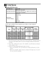
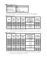
Page 8: ...but images may be cut off if they do not match the sampling Size H Sync kHz V Sync Hz Dot Clock MHz Screen Resolution Expansion H Horizontal V Vertical Display Resolution 640 350 1 31 469 70 000 25 175 640 420 640 400 31 469 70 000 25 175 640 480 640 400 24 827 56 420 21 053 640 480 640 480 31 469 59 992 25 175 1 0 640 480 720 350 1 2 3 31 469 70 000 28 320 640 420 720 400 2 3 31 469 70 000 28 320...

Page 9: ...ecified Analog RGB cable is used FP unit operation cannot be guaranteed due to the possibility of noise interference Size H Sync kHz V Sync Hz Dot Clock MHz Screen Resolution Expansion H Horizontal V Vertical Display Resolution 640 350 1 31 469 70 000 25 175 800 525 640 400 31 469 70 000 25 175 800 600 640 400 24 827 56 420 21 053 800 600 640 480 31 469 59 992 25 175 800 600 640 480 35 000 66 670 ...

Page 10: ...720 x 400 Display Resolution 720 x 400 DSP in System Setting of the OSD On Screen Display DVI D Interface Input signal type DVI D Setting by OSD On Screen Display H POS V POS BACKLIGHT DEFAULT ALL CLEAR The FP unit s available screen resolutions are as follows Unit dot pixel Size H Sync kHz V Sync Hz Dot Clock MHz Screen Resolution Expansion H Horizontal V Vertical Display Resolution 640 400 31 46...

Page 11: ... TMDS DATA1 21 NC 10 TMDS DATA1 22 TMDS CLOCK SHIELD 11 TMDS DATA1 3 SHIELD 23 TMDS CLOCK 12 NC 24 TMDS CLOCK DVI D Pin Assignments and Signal Names Connector DVI D 24 pin male Connector set screw Inch type 4 40 DVI DCable FP DV01 50 5m ManufacturedbyDigitalElectronicsCorporationofJapan If a cable other than the specified DVI D cable is used FP unit operation cannot be guaranteed due to the possib...

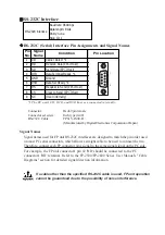
Page 12: ...ignal names used for FP unit RS 232C interfaces are designed to match the pin order used on most PC serial connectors which allows a straight cable to be used to connect the two Therefore connect each FP connector pin s signal to the same signal signal on the PC side For example the FP unit connector s pin 2 RD should be connected to the PC connector s RD terminal Refer to the FP 2500 FP 2600 Seri...

Page 13: ... resistance Be sure to change the gasket periodically or when scratches or dirt become visible Be sure to use gasket model GP570 WP10 MS Be sure the gasket s seam is not inserted into any of the unit s corners only in the straight sections of the groove Inserting it into a corner may lead to its eventually tearing To ensure the installation gasket s maximum level of moisture resistance be sure the...

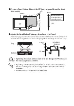
Page 14: ...GP070 AT01 FP Panel Attach the Installation Fasteners from Inside the Panel The following figures show the four 4 fastener insertion slot locations Insert each fastener s hook into the slot Tighten the screws in a diagonal pattern and slowly increase the torque Unit mm in Create a Panel Cut and insert the FP into the panel from the front Panel 301 5 11 87 1 0 0 04 0 227 5 8 96 1 0 under 4 R3 FP 0 ...

Page 15: ...er switch on the FP unit be sure to attach a breaker type switch to its power cord 1 Suggested Ring Terminal equivalent to V2 MS3 made by JST When the FG terminal is connected be sure the wire is grounded Not grounding the FP unit will result in excess noise and vibration Rear of FP Ring Terminals 1 Power Input Terminal Block FG FG Connecting the AC Power Cord When connecting the power cord be sur...

Page 16: ...the power supply voltage exceeds the FP unit s specified range connect a voltage transformer Between the line and the ground be sure to use a low noise power supply If there is still an excessive amount of noise connect a noise reducing transformer Input and Output signal lines must be separated from the power control cables for operational circuits The FP unit s power supply cord should not be bu...

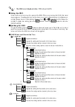
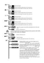
Page 17: ...s settings such as activating the click sound ESCAPE Cancels the setting and returns to the upper level In the main menu this command closes the OSD Item 1 When using DVI D the message DO NOT NEED SETUP FOR DVI D is displayed and no settings are required OSD Features Use the FP unit s touch panel and the OSD On Screen Display menu to set the FP screen settings and fine tune your screen s display Y...

Page 18: ...cels the setting and then returns to the main menu H POS SET Applies the setting and then returns to the main menu Adjustment buttons ESC Cancels the setting and then returns to the sub contrast adjustment screen ESC Returns to the contrast menu B B contrast Adjustment buttons SET Applies the setting and then returns to the sub contrast adjustment screen SET Applies the setting and then returns to...

Page 19: ...sables the click sound With this parameter the sound level can also be adjusted Default value OFF Click sound disabled Select the time period from 1min 3min 5min 10min and OFF Auto OFF function disabled 720 400 DSP When an input data resolution of 720 X 400 is used in the VGA text mode set this parameter to ON For other resolutions set this parameter to OFF Default OFF AUTO OFF DSP Enables disable...

Page 20: ...ablebytheuserforany damages losses or third party claims arising from the uses of this product FP Model No Backlight Model No FP2500 T42 24V GP577RT BL00 MS FP2600 T42 24V PS600 BU00 In the system setting screen touching the value displayed on the panel changes the value of the time period Normally the FP unit detects a backlight burnout by monitoring the backlight s current flow however the FP ma...

Reviews: