FP2600-T41 User Manual
Specifications
2-5
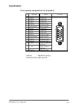
Pin
No.
Signal Name
Condition
Pin Location
1
Analog R
R signal input
2
Analog G
G signal input
3
Analog B
B signal input
4
Reserved
NC (spare for input)
5
Digital grounding
Digital signal GND
6
Return R
R signal GND
7
Return G
G signal GND
8
Return B
B signal GND
9
Reserved
NC (spare for input)
10
Digital grounding
Digital signal GND
11
Reserved
NC (spare for input)
12
Reserved
NC (spare for input)
13
H. SYNC
Horizontal synchronous
signal input
14
V. SYNC
Vertical synchronous
signal input
15
Reserved
NC (spare for input)
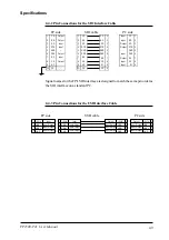
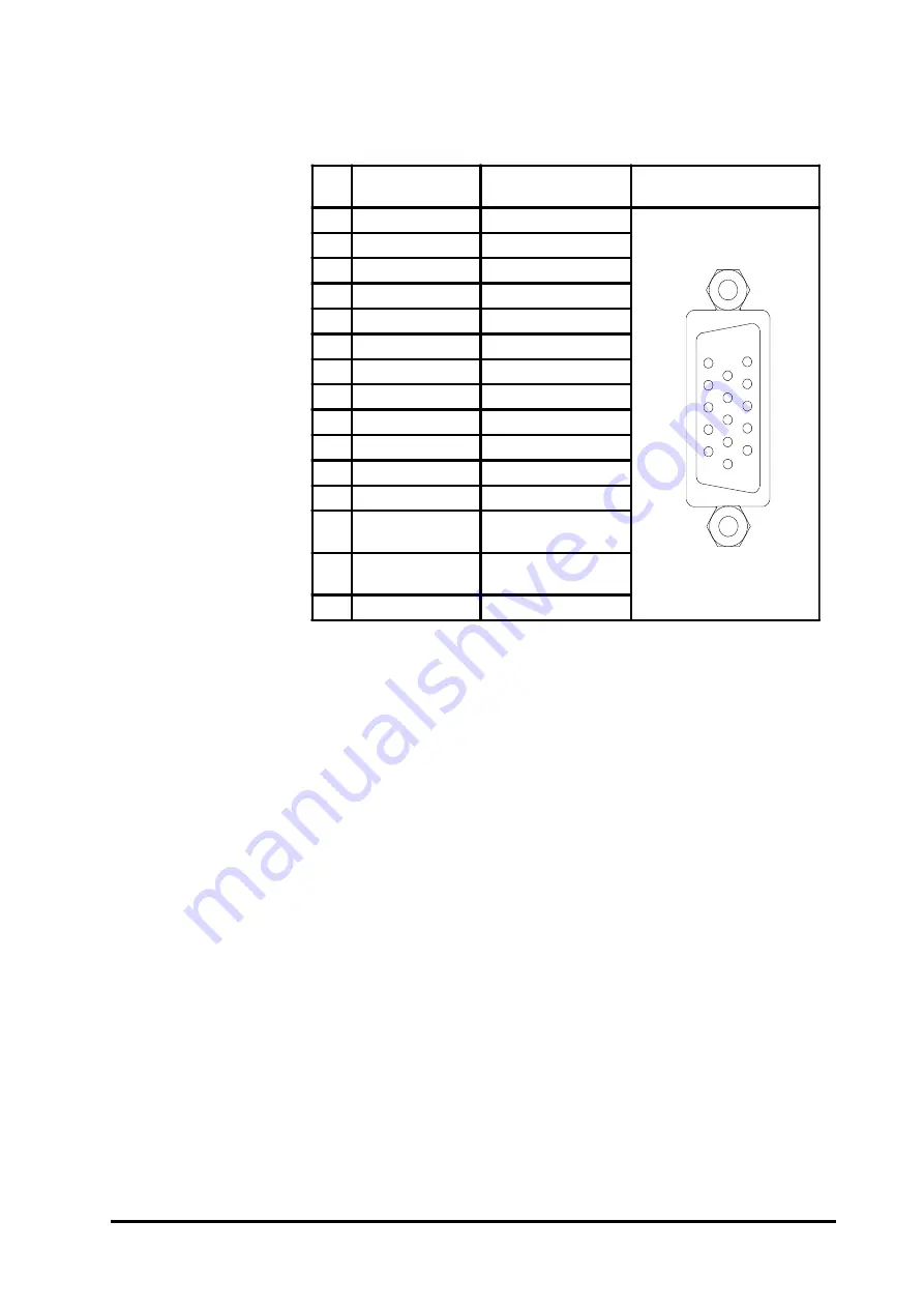
Pin Assignments and Signal Names for Analog RGB
Connector:
Mini Dsub 15 pin type
Connector set screw: Inch type (4-40)
11
15
1
5

