12345678901234567890123456789012
12345678901234567890123456789012
12345678901234567890123456789012
12345678901234567890123456789012
12345678901234567890123456789012
12345678901234567890123456789012
12345678901234567890123456789012
12345678901234567890123456789012
12345678901234567890123456789012
12345678901234567890123456789012
12345678901234567890123456789012
12345678901234567890123456789012
12345678901234567890123456789012
12345678901234567890123456789012
12345678901234567890123456789012
12345678901234567890123456789012
12345678901234567890123456789012
12345678901234567890123456789012
12345678901234567890123456789012
12345678901234567890123456789012
12345678901234567890123456789012
C h a p t e r 3
Installation and Wiring
1. Installation
2. Wiring
3. Operation Mode Setup and Display Positioning
Confirm the Installation Gasket's Positioning
It is strongly recommended that you use the gasket. It absorbs vibration in addition to
repelling water.
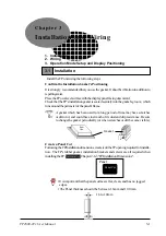
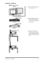
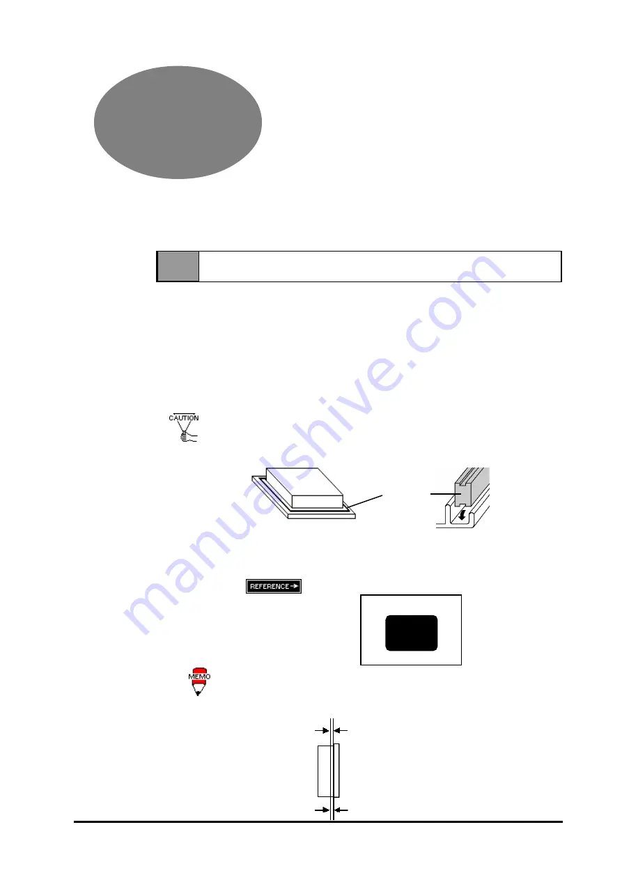
Place the FP on a level surface with the display panel facing downward.
Check that the FP's installation gasket is seated securely into the gasket's groove, which
runs around the perimeter of the panel's frame.
Create a Panel Cut
Following the FP Installation dimensions, create (cut) the FP opening required for installa-
tion. The FP's rubber gasket, installation brackets and screws are all required when
installing the FP.
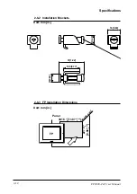
Chapter 2-6-3 "FP Installation Dimensions".
• It is important that the panel surface is flat, clean, and has no jagged
edges.
• The Panel thickness should be between 1.6mm and 10.0mm.
A gasket which has been used for a long period of time may have scratches
or dirt on it, and could have lost much of its dust and drip resistance. Be sure
to change the gasket periodically (or when scratches or dirt become visible).
Rear
View
Gasket
Panel Cut
Panel
1.6 to 10mm
3-1
FP2600-T41 User Manual
3-1 Installation
Install the FP unit using the following steps.

