Device Connectivity
24
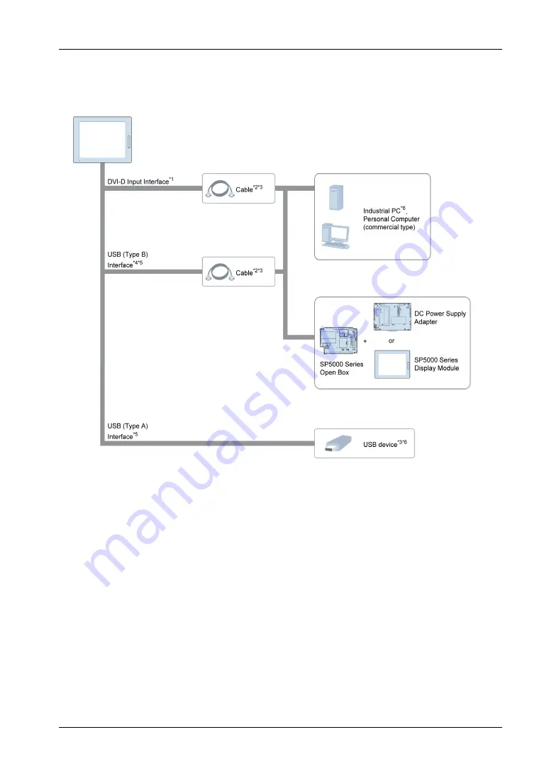
System Design
*1 For image signal reception.
*2 Refer to Accessories
.
*3 You can also use a commercial type.
*4 For touch panel data transmission.
*5 When you connect a USB (Type B) interface to the host with a USB cable, you can use the front
USB (Type A) interface.
*6 You can use Pro-face products. Refer to our website (
http://www.pro-face.com
).
NOTE:
When you connect more than one display to the host in the following combinations, a touch
operation on one display prevents touch operations on the other.
This P This Product
This P SP5000 Series Display Module
Be careful when you connect displays in any other combination, as touch operations become
possible from any of the displays.
Summary of Contents for FP5000 Series
Page 1: ...FP5000 Series User Manual FP5000 MM01 EN PDF_02...
Page 6: ...6...
Page 10: ...10...
Page 22: ...Overview 22 KC Markings...
Page 26: ...Device Connectivity 26...
Page 30: ...Parts Identification and Functions 30...
Page 48: ...Dimensions 48 FP 5600TPD External Dimensions 1 Front 2 Left 3 Bottom...
Page 50: ...Dimensions 50 FP 5700TPD External Dimensions 1 Front 2 Left 3 Bottom...
Page 52: ...Dimensions 52...
Page 72: ...Installation and Wiring 72...


