6
Wiring
•
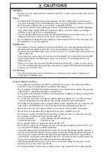
To avoid an electric shock, when connecting the GP's power cord
terminals to the power terminal block, confirm that the GP's power
supply is completely turned OFF, via a breaker, or similar unit.
•
GP2500-TC11 and GP2600-TC11 units that are not marked as REV
"3" are designed for use only with 100 VAC input.
•
Since there is no power switch on the GP unit, be sure to attach a
breaker-type switch to its power cord.
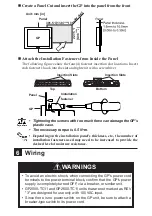
under 4-R3
Panel
Unit: mm [in]
Installation
fastener
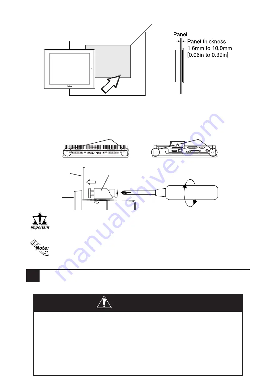
Create a Panel Cut and insert the GP into the panel from the front
Attach the Installation Fasteners from Inside the Panel
The following figures show the four(4) fastener insertion slot locations. Insert
each fastener's hook into the slot and tighten it with a screwdriver.
Panel
GP
• Tightening the screws with too much force can damage the GP's
plastic case.
• The necessary torque is 0.5 N•m.
• Depending on the installation panel's thickness, etc., the number of
installation fasteners used may need to be increased to provide the
desired level of moisture resistance.
Insertion Slots
Insertion Slots
Top
Bottom
301.5 [11.87 ]
+1
0
+0.04
0
227.5
[8.96 ]
+0.04
0
GP
WARNINGS
+1
0


