
•
To avoid a short caused by loose ring terminals, be sure to use
ring terminals with an insulating sleeve.
•
When the FG terminal is connected, be sure the wire is grounded.
Not grounding the GP unit will result in excess noise and vibra-
tion.
• Wherever possible, use thick wires (max. 2 mm
2
) for power termi-
nals, and twist the wire ends before attaching the ring terminals.
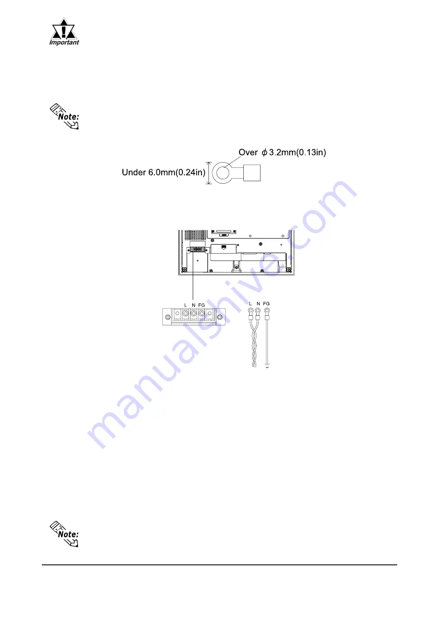
• Be sure to use the following size ring terminals.
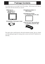
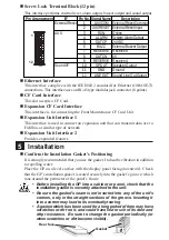
*1
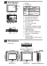
Power Input
Terminal Block
Rear of GP
Ring Terminals*
1
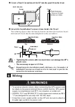
Connecting the GP Power Cord
When connecting the power cord, be sure to follow the procedures given below.
1. Confirm that the GP's Power Cord is unplugged from the power supply.
2. Use a screwdriver to remove the Power Input Terminal Block's clear plastic
cover.
3. Unscrew the screws from the middle three (3) terminals, align the Ring Terminals
and re-attach the screws.
4. Replace the Power Input Terminal Block's clear plastic cover.
• Confirm that the ring terminal wires are connected correctly.
• The torque required to tighten these screws is 0.5 to 0.6 N•m.
*1
L=AC Input Live Line
N=AC Input Neutral Line
FG=Grounding Terminal connected to the GP chassis.
Suggested Ring Terminal : equivalent to V2-MS3 (made by JST)


