
CAUTIONS
Installation
•
Be sure to securely connect all cable connectors to the GP. A loose connection may cause incorrect
input or output.
Wiring
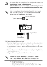
•
Ground the GP's FG line separately from other units’ FG lines. Putting these FG lines too close
may cause an electric shock or unit malfunction. Be sure to use a grounding resistance of 100
Ω
or
less and a 2mm
2
or thicker wire, or your country’s applicable standard.
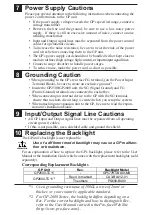
•
Correctly wire the GP, be sure that the rated voltage and terminal layout are within the designated
range. If the voltage supplied differs from the rated voltage, or incorrect wiring or grounding is
performed, it may cause a fire or unit malfunction.
•
Use only the designated torque to tighten the GP's terminal block screws. If these screws are not
tightened firmly, it may cause a short-circuit, fire, or GP malfunction.
•
Be careful that metal filings and wiring debris do not fall inside the GP, since they can cause a fire,
GP malfunction, or incorrect operation.
Maintenance
•
The liquid crystal panel contains a powerful irritant and if for any reason the panel is damaged and
this liquid contacts any part of your body, be sure to wash that area with running water for 15
minutes. If any of this liquid enters your eye, flush your eye for 15 minutes with running water and
contact a physician.
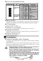
•
Prior to inserting or removing a CF Card, be sure to turn the GP’s CF Card ACCESS switch OFF
and to confirm that the ACCESS lamp is not lit. If you do not, CF Card internal data may be
damaged or lost.
•
While a CF Card is being accessed, NEVER turn OFF or reset the GP, or insert or remove the CF
Card. Prior to performing these operations, create and use a special GP application screen that will
prevent access to the CF Card.
Unit Disposal
•
When this unit is disposed of, it should be done so according to your country's regulations for
similar types of industrial waste.
General Safety Precautions
•
Do not strike the touch panel with a hard or pointed object, or press on the touch panel with too
much force, since it may damage the touch panel or the display.
•
Do not install the GP where the ambient temperature can exceed the allowed range. Doing so may
cause the GP to malfunction or shorten its operation life.
•
Do not restrict or limit the GP’s naturally occurring rear-face ventilation, or storing or using the GP
in an environment that is too hot.
•
Do not use this unit in areas where large, sudden temperature changes can occur. These changes
can cause condensation to form inside the unit, possibly causing the unit to malfunction.
•
Do not allow water, liquids, metal or charged particles to enter inside the GP’s case, since they can
cause either a GP malfunction or an electrical shock. The allowable pollution degree is 2.
•
Do not use or store the GP in direct sunlight, or in excessively dusty or dirty environments.
•
Do not store or use the unit where strong jolting or excessive vibration can occur.
•
Do not store or use the GP where chemicals (such as organic solvents, etc.) and acids can evapo-
rate, or where chemicals and acids are present in the air.
Corrosive chemicals:
Acids, alkalines, liquids containing salt
Flammable chemicals:
Organic Solvents
•
Do not use paint thinner or organic solvents to clean the GP.
•
Do not store or operate the LCD display in areas receiving direct sunlight, since the sun's UV rays
may cause the LCD display’s quality to deteriorate.
•
Storing this unit in areas at a temperature lower than is recommended in this manual’s specifica-
tions may cause the LCD display’s liquid to congeal, which may damage the panel. Conversely, if
the storage area’s temperature becomes higher than the allowed level, the LCD’s liquid will be-
come isotropic, causing irreversible damage to the LCD. Therefore, be sure to store the panel only
in areas where temperatures are within those specified in this manual.
•
After turning the GP OFF, be sure to wait a few seconds before turning it ON again. If the GP
started too soon, it may not start up correctly.
•
Due to the possibility of unexpected accidents, be sure to back up the GP’s screen data regularly.


