background image

The GP2500-TC11

*1

 and the GP2600-TC11

*1

 are UL/c-UL(CSA) recognized

components. (UL file No. E231702)
This Unit conforms as a component to the following standards:

„

„

„

„

„

UL1604

Electrical Equipment for Use in Class I and II Division 2 and Class III Hazard-
ous (Classified) Locations

„

„

„

„

„

UL60950

Safety Standard for Information Technology Equipment (3rd Edition, issued
December 1, 2001)

„

„

„

„

„

CAN/CSA-C22.2, No.60950-00

Safety Standard for Information Technology Equipment (3rd Edition, issued
December 1, 2001)

„

„

„

„

„

CAN/CSA-C22.2, No.213-M1987

Safety Standard for Information Technology and Electrical Business Equipment

GP2500-TC11 (UL Registration Model : 3180021-01)
GP2600-TC11 (UL Registration Model : 3180021-02)

<Cautions>

  The GP must be used as a built-in component of an end-use product.

  The GP units must be used indoors only.

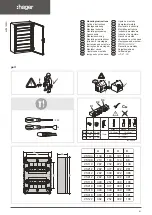
  The GP should be installed in the front face of a metal panel.

  If the GP is installed so as to cool itself naturally, be sure to install it in a verti-

cal panel. Also, be sure that the GP is mounted at least 100mm away from
adjacent structures and other equipment, otherwise, the heat generated by the
GP's internal components may become higher than that allowed by UL stan-
dard requirements.

  Make sure to set up a switch to turn off the power to the GP in an accessible

position on the end-use product that the GP unit is built-in. Make sure to
consider the current and voltage when selecting the switch.

  Make sure that the frame of the product to which the GP unit is built-in con-

forms to UL60950 standard requirements.

UL1604 Conditions of Acceptability and Handling Cautions:

1. Power, input and output (I/O) wiring must all be in accordance with Class I,

Division 2 wiring methods, Article 501-4 (b) of the National Electrical  Code,
NFPA 70, or as specified in Section 18-152 of the Canadian Electrical Code
for units installed within Canada, and in accordance with that location's au-
thority.

2. Suitable for use in Class I, Division2, GroupsA, B, C and D hazardous loca-

tion.

3. 

WARNING:

 Explosion hazard - substitution of components may impair

suitability for Class I, Division2.

4. 

WARNING:

 Explosion hazard - when in hazardous locations, turn the power

off before replacing or wiring modules.

5. 

WARNING:

 Explosion hazard - do not disconnect equipment unless power

has been switched off or the area is known to be nonhazardous.

6. 

WARNING

: Explosion hazard - do not connect/ disconnect equipment unless

area is known to be nonhazardous. Port is for system set up and diagnostics.

UL/c-UL(CSA) Approval

Summary of Contents for GP2500-TC11

Page 1: ...iability and safety After the GP s backlight burns out unlike the GP s Standby Mode the touch panel is still active If the operator fails to notice that the backlight is burned out and touches the panel a potentially dangerous machine miss operation can occur Therefore do not use GP touch switches for the control of any equipment safety mechanisms such as Emergency Stop switches etc that protect h...

Page 2: ...ith a hard or pointed object or press on the touch panel with too much force since it may damage the touch panel or the display Do not install the GP where the ambient temperature can exceed the allowed range Doing so may cause the GP to malfunction or shorten its operation life Do not restrict or limit the GP s naturally occurring rear face ventilation or storing or using the GP in an environment...

Page 3: ...her than that allowed by UL stan dard requirements Make sure to set up a switch to turn off the power to the GP in an accessible position on the end use product that the GP unit is built in Make sure to consider the current and voltage when selecting the switch Make sure that the frame of the product to which the GP unit is built in con forms to UL60950 standard requirements UL1604 Conditions of A...

Page 4: ...rnal components may become higher than that allowed by the stan dard requirements Make sure to set up a switch to turn off the power to the GP in an accessible position on the end use product that the GP unit is built in Make sure to consider the current and voltage when selecting the switch Make sure that the frame of the product to which the GP unit is built in con forms to EN60950 standard requ...

Page 5: ... packed with special attention to quality However should you find anything damaged or missing please contact your local GP distributor im mediately Package Contents GP Unit 1 GP2500 TC11 GP2600 TC11 Installation Guide 1 This Guide Installation Gasket 1 attached to the GP unit Installation Fasteners 4 set Screw Lock Terminal Block 1 attached to the GP unit ...

Page 6: ... Unit Interface 2 G CF Card Expansion Interface H CF Card Cover I CF Card Access Lamp J CF Card Slot K Serial Interface HOST I F 25 pin L Serial Interface SUB SIO 9 pin M Printer Interface Half Pitch 20 pin N Ethernet Interface 10BASE T O Screw Lock Terminal Block 12 pin P Tool Connector Connects a Data Transfer Cable or bar code reader LED GP Status Not Lit Power is OFF Green Normal operation Ora...

Page 7: ...ion ON OFF Note 1 This Dip switch setting controls the startup from a CF Card Startup from CF Card is enabled Startup from CF Card is disabled CF Card with startup data required 2 Reserved 3 Reserved 4 This setting controls the forced closing ofthe CF Card cover Forced close enabled Forced close disabled Used when CF Card cover is damaged Keep these switches OFF ...

Page 8: ...g XM2A 2501 made by OMRON Corp Recommended Cover Dsub 25 pin Cover XM2S 2511 made by OMRON Corp Jack Screw XM2Z 0071 made by OMRON Corp Recommended Cable CO MA VV SB5P x 28AWG made by HITACHI Cable Ltd This GP unit s serial port is not isolated When the host PLC unit is also not isolated and to reduce the risk of damaging the RS 422 circuit be sure to connect the 7 SG Signal Ground terminal Pin 14...

Page 9: ...422 For RS 232C Connectors Do not connect 9 TRMX 10 RDA 11 SDA 15 SDB 16 RDB 18 CSB 19 ERB 21 CSA and 22 ERA The 1 FG terminal should only be connected if it is required by the device being connected to Serial Interface SUB SIO Connect a Serial Bar code reader or a 2 Dimensional code reader to this interface Printer Interface Half Pitch 20 pin When connecting a printer use Digital s printer cable ...

Page 10: ... the straight sections of the groove Inserting it into a corner may lead to its eventually tearing A gasket which has been used for a long period of time may have scratches or dirt on it and could have lost much of its dust and drip resistance Be sure to change the gasket periodically or when scratches or dirt become visible Confirm the Installation Gasket s Positioning It is strongly recommended ...

Page 11: ...ner Create a Panel Cut and insert the GP into the panel from the front Attach the Installation Fasteners from Inside the Panel The following figures show the four 4 fastener insertion slot locations Insert each fastener s hook into the slot and tighten it with a screwdriver Panel GP Tightening the screws with too much force can damage the GP s plastic case The necessary torque is 0 5 N m Depending...

Page 12: ...P Power Cord When connecting the power cord be sure to follow the procedures given below 1 Confirm that the GP s Power Cord is unplugged from the power supply 2 Use a screwdriver to remove the Power Input Terminal Block s clear plastic cover 3 Unscrew the screws from the middle three 3 terminals align the Ring Terminals and re attach the screws 4 Replace the Power Input Terminal Block s clear plas...

Page 13: ...ial attention to the following instructions when connecting the power cord terminals to the GP unit If the power supply voltage exceeds the GP s specified range connect a voltage transformer Between the line and the ground be sure to use a low noise power supply If there is still an excessive amount of noise connect a noise reducing transformer Input and Output signal lines must be separated from ...

Reviews: