3 - 12
PL-6700 Series User’s Manual
Optional Units and Expansion Boards
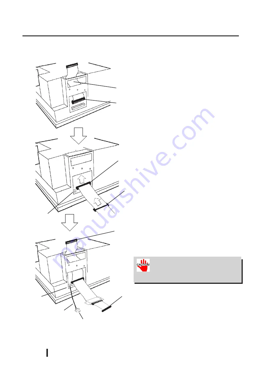
4) Disconnect the HD connection cable
from the Main Board’s HDD con-
nector.
6) Connect the PL-SA100’s additional
DC power cable to the DC OUT
connector.
5) Thread the PL-SA100 connection
cable’s PL-HD100 cable conector
through the slot shown here and up
through to the top of the chassis.
Then, connect the cable’s middle
connector to the main board’s
HDD connector.
Be sure to connect the CD-ROM drive
connector cable’s #1 pin mark side
with the IDE interface’s #1 pin.
DC Power Cable
Connect to
DC Input
Connect to
C D - R O M
drive
C o n n e c t t o
PL-HD100
DC Out
Connector
Middle Connector
(Insert into main board’s
HDD connector)
PL-SA100
I n s e r t t h e P L -
HD100 connec-
tor here
HDD Connector
HD Connection cable
7) Last, connect the PL-HD100 to the
end of the cable and use the attach-
ment screws to fix the HD unit in
place. (Refer to page 3-10, Step 2)
DC Out
Connector
Summary of Contents for PL-6700 Series
Page 1: ...PL 6700 Series Panel Computer User s Manual Digital Electronics Corporation...
Page 19: ...1 4 PL 6700 Series User s Manual Overview MEMO This page intentionally left blank...
Page 29: ...2 10 PL 6700 Series User s Manual Chapter 2 Specifications Rear Face Top Face 330...
Page 69: ...6 2 PL 6700 Series User s Manual Bundled Software MEMO This page intentionally left blank...
Page 73: ...Maintenance and Inspection 7 4 PL 6700 Series User s Manual MEMO...


