Chapter 2 - PLC-GP Connection
2-22-2
2.22 ORIM VEXTA
GP-PRO/PBIII for Windows Device/PLC Connection Manual
2.22.3
Supported Devices
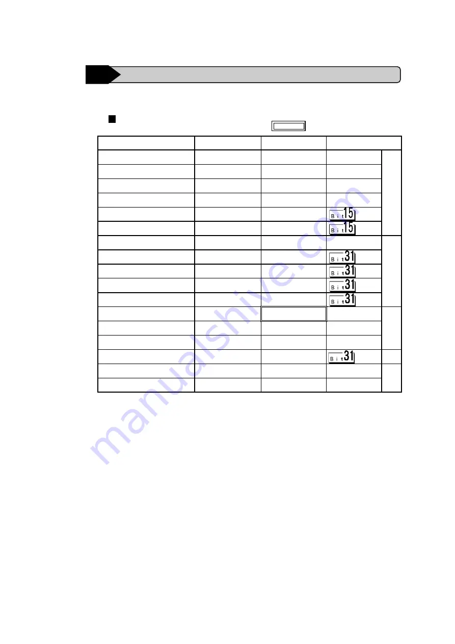
The following describes the range of devices supported by the GP.
Device
Bit Address
Word Address
Particulars
Input Register (I)
I000100 ~ I000815
I0001 ~ I0008
L/H
ON Event Input Register(IU)
IU00100 ~ IU00815
IU001 ~ IU008
*2
OFF Event Input Register(ID)
ID00100 ~ ID000815
ID001 ~ ID008
*2
Output Register(O)
O000100 ~ O000815
O0001 ~ O0008
Analog Input Register(AD)
-------
AD001 ~ AD008
*2
Analog Output Register(DA)
-------
DA001 ~ DA008
Position Register (M)
M000100 ~ M010031
M0001 ~ M100
*3
H/L
Speed Register Low(SL)
-------
SL001 ~ SL100
*3
Speed Register High(SH)
-------
SH001 ~ SH100
*3
Speed Register Raise(SR)
-------
SR001 ~ SR100
*3
Speed Register Decrease(SD)
-------
SD001 ~ SD100
*3
Universal Register(R)
R000100 ~ R100015
R0001 ~ R1000
L/H
Universal Double-Length Register(RD)
RD00100 ~ RD50031
RD001 ~ RD500
*3
Base Resister (B)
B000000 ~ B000915
B0000 ~ B0009
Current Motor Position(MP)
-------
MP001~MP008
*3 *2
H/L
Current Motor Status(MP)
MS00100 ~ MS00815
MS001 ~ MS008
*2
L/H
SY Register(SY)
SY00100 ~ SY10015
SY001 ~ SY100
*1 *2
*1 For further information about SY register, refer to ORIM VEXTA’s Motion Con-
troller E1 Series Operation manual.
*2 Data cannot be written to here.
*3 This device is 32 bit.
E1 Series
Setup System Area here.


