11
*1
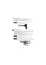
The VCC output is not protected against overcurrent.
To prevent damage or a unit malfunction, use only the rated current.
RAS Interface
RAS Interface. A D-sub 15-pin plug connector is used.
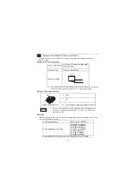
Ethernet Interface
The Ethernet transmission interface conforms to IEEE802.3u (10BASE-T/100BASE-TX).
An RJ-45 type modular jack connector (8-pole) is used.
Pin Arrangement
Pin No.
RS-232C
Signal Name Direction
Meaning
1
NC
Input
Not Connected
2
RD(RXD)
Input
Receive Data
3
SD(TXD)
Output
Send Data
4
NC
Output
Not Connected
5
SG
-
Signal Ground
6
NC
Input
Not Connected
7
RS(RTS)
Output
Request to Send
8
CS(CTS)
Input
Send Possible
9
VCC
-
+5V
±
5% Output 0.25A
*1
Shell
FG
-
Frame Ground
(Common with SG)
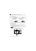
PS-G Connector
XM2C-1542-502L <OMRON Co.>
Stacking Metal Fittings
M2.6 (metric screw thread) screws
Recommended cable
Connector
XM2D-1501 <OMRON Co.>
Recommended cable Cover XM2S-1511 <OMRON Co.>
Pin Arrangement
Pin No.
Signal Name
Meaning
1
ALARM-OUT (-)
Alarm Output (-)
2
DOUT (-)
General-purpose Output (-)
3
RESET-IN (-)
Remote Reset Input (-)
4
DIN (-)
General-purpose Input (-)
5
ALARM-OUT (+) Alarm Output (+)
6
DOUT0 (+)
General-purpose Output 0 (+)
7
DOUT1 (+)
General-purpose Output 1 (+)
8
DOUT2 (+)
General-purpose Output 2 (+)
9
DOUT3 (+)
General-purpose Output 3 (+)
10
RESET-IN (+)
Remote Reset Input (+)
11
DIN0 (+)
General-purpose Input 0(+)
12
DIN1 (+)
General-purpose Input 1 (+)
13
DIN2 (+)
General-purpose Input 2 (+)
14
DIN3 (+)
General-purpose Input 3 (+)
15
NC
No Connection
5
1
9
6
8
1
15
9


