16
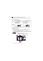
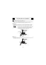
Connect the power cord to the Power Input Terminal Block on the Rear of the PS-G unit.
Power Cord Specifications
*1 In order to prevent a short circuit caused by loose screws, make sure to use a crimp-type
terminal with insulating sleeve.
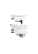
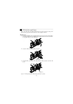
Connecting the Power Cord
When connecting the AC type power cord, be sure to follow the procedures given below.
(1) Be sure that the PS-G’s power cord is not plugged in to the power supply.
(2) Remove the Terminal Srtip’s clear plastic cover.
(3) Remove the screws from the two (2) terminals (L,N) and FG (Frame Ground) Terminal,
position the Ring Terminals and reattach the screws. (Check each wire to make sure the
connections are correct.)
(4) Reattach the Terminal Strip’s clear plastic cover.
1
Wiring for the PS3600G-T41 unit (AC100 to 240V)
AC Power Cord
Grounding Wire
Power Cord
Double-insulated Wire
1.25 to 2.0 mm
2
[0.0024 to 0.0062
inch
2
] (16 to 14 AWG)
1.25 to 2.0 mm
2
[0.0024 to 0.0062
inch
2
] (16 to 14 AWG)
Recommended
Ring Terminal
*1
V2-MS3 compatible
(J.S.T. Mfg. Co., Ltd)
V2-P4 compatible
(J.S.T. Mfg. Co., Ltd)
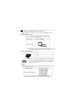
• The torque required to tighten these screws are as follows:
Terminal Block: 0.5 to 0.6N
•
m
FG (Frame Ground) Terminal: 0.6 to 0.7N
•
m
less than
6mm [0.24 in.]
3.2mm [0.13 in.]
or more
less than
7mm [0.28 in.]
4.3mm [0.17 in.]
or more
DON’T
CONNECT
FG (Frame Ground) Terminal


