PS-4600 Series User Manual
121
4
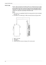
Connect the UPS Connection Cable to the UPS Battery Unit, whereby the red and
black wires are connected to the supply voltage (orange screw clamp terminal
block). Be sure to use the right connection terminals (red wire for +; black wire for -).
5
Connect the white and brown wires to the temperature sensor (green screw clamp
terminal block) (white wire for 1; brown wire for 2):
1
White wire temperature sensor
2
Brown wire temperature sensor
3
Temperature sensor screw clamp terminal block
4
Battery screw clamp terminal block
6
Tighten the connected wires in the screw clamps with a screwdriver (to a max. tight-
ening torque of 0.4 Nm).
7
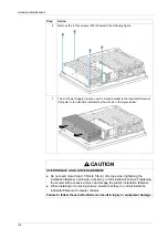
Connect the 4-pin screw clamp to the UPS Interface Board and tighten the two
screws with a screwdriver (max. torque 0.4 Nm).
CAUTION
OVERTORQUE AND LOOSE HARDWARE
Do not exert more than 0.5 Nm (4.5 lb-in) of torque when tightening the
installation fastener, enclosure, accessory, or terminal block screws. Tightening
the screws with excessive force can damage the plastic installation fastener.
When installing or removing screws, ensure that they do not fall inside the
Industrial Personal Computer chassis.
Failure to follow these instructions can result in injury or equipment damage.
Step
Action
4
3
+
–
1
2
Summary of Contents for PS-4600 Series
Page 1: ......
Page 12: ...About the Book 12...
Page 14: ...General Overview 14...
Page 26: ...Important Information 26...
Page 56: ...Implementation 56...
Page 72: ...Industrial Personal Computer Connections 72...
Page 78: ...Configuration of the BIOS 78 Platform Information The figure shows the Main submenu...
Page 118: ...Hardware Modifications 118 The figure shows the dimensions of the UPS battery unit...
Page 170: ...Hardware Modifications 170...
Page 172: ...Installation 172...
Page 192: ...192...
Page 196: ...After sales service 196...


