Assembly Instructions
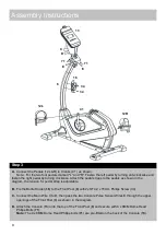
A.
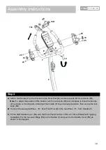
Attach the Handle (
7
) to the bracket on the Front Post (
6
), and secure with M10 Lock knob (
10
).
Note:
To adjust the position of the handle, turn the lock knob (
10
) anti clockwise to loose the handle
(
7
) as shown in the diagram, and adjust the handle (
7
) to your required position, then secure the lock
knob (
10
).
B.
Connect the two signal Wires
(
E
)
from Front Post (
6
) to the two Wires
(
F
)
from Handle (
7
).
C.
Fit the L&R Handle Cover (
15
) onto the Front Post (
7
) with 4 x ST4.2 x 15mm Phillips Self Tapping
Screw(
63
). Put the two Joint Rings (
74
) on the Handle (
7
) and push to the Handle Cover (
15
) as
shown in the diagram.
Step 4
10
74
15L
25
25
6
25
25
74
7
10
15R
E
E
F
F
Summary of Contents for 782/3792
Page 31: ...Exploded Parts Diagram 30...


