background image

22

Key No. Qty.

Description

Key No. Qty.

Description

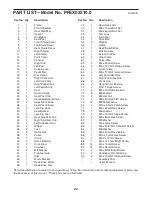
PART LIST—Model No. PFEX02210.0

R0610B

Note: Specifications are subject to change without notice. For information about ordering replacement parts, see

the back cover of this manual. *These parts are not illustrated.

1

1

Frame

2

1

Front Stabilizer

3

1

Rear Stabilizer

4

1

Upright

5

1

Handlebar

6

1

Seat Post

7

1

Front Shield Cover

8

1

Top Shield Cover

9

1

Rear Shield Cover

10

1

Right Shield

11

1

Left Shield

12

1

Pivot Cover

13

1

Console

14

1

Right Pad

15

1

Left Pad

16

1

Pulse Sensor

17

2

Pedal Disc

18

2

Disc Cover

19

1

Right Crank Arm

20

1

Left Crank Arm

21

1

Right Pedal/Strap

22

1

Left Pedal/Strap

23

1

Seat

24

1

Seat Carriage

25

2

Seat Post Cap

26

1

Seat Adjustment Knob

27

2

Adjustment Knob

28

1

Seat Post Sleeve

29

2

Leveling Knob

30

1

Seat Bracket

31

2

Leveling Foot

32

2

Rear Stabilizer Cap

33

1

Right Stabilizer Cap

34

1

Left Stabilizer Cap

35

2

Wheel

36

2

Foot

37

2

Game Grip

38

1

Pulley

39

1

Crank

40

2

Crank Bearing

41

2

Snap Ring

42

1

Flywheel

43

2

M8 Washer

44

1

Flywheel Axle

45

1

Idler

46

1

Motor Bracket

47

1

Resistance Motor

48

1

Resistance Disc

49

1

Resistance Arm

50

1

M6 x 70mm Bolt Set

51

1

M6 x 60mm Bolt Set

52

1

Arm Lock

53

1

C-magnet

54

1

Drive Belt

55

2

Magnet

56

1

Clamp

57

1

Reed Switch/Wire

58

1

Wire Harness

59

1

Extension Wire

60

2

Wire Clamp

61

1

Pulse Wire

62

2

M4 x 25mm Screw

63

2

M4 x 12.7mm Flange Screw

64

1

Audio Cable

65

3

M8 x 17mm Flat Head Screw

66

1

Left Controller Wire

67

1

Right Controller Wire

68

2

Crank Cap

69

2

Upright Pivot Bushing

70

2

5/16" Flange Screw

71

4

M8 x 20mm Button Bolt

72

8

M8 Locknut

73

2

M8 Jam Nut

74

4

M8 x 20mm Patch Screw

75

12

M8 Split Washer

76

4

M10 x 95mm Patch Screw

77

1

M6 x 65mm Hex Screw

78

1

M6 Locknut

79

4

M4 x 12mm Flange Screw

80

2

M6 x 8mm Hex Screw

81

1

M5 Washer

82

1

M5 x 7mm Screw

83

1

M6 x 14.67mm Shoulder Screw

84

1

M6 Washer

85

1

M6 x 20mm Hex Screw

86

1

M10 x 50mm Hex Screw

87

1

M3.5 x 12mm Screw

88

1

M4 x 12.7mm Bright Screw

89

14

M4 x 19mm Screw

90

12

M4 x 16mm Screw

91

2

M4 x 5mm Bright Screw

92

2

Handlebar Pivot Bushing

93

6

M4 x 19mm Flat Head Screw

*

Assembly Tool

*

Userʼs Manual

Summary of Contents for 200 CSX

Page 1: ...e space above for future reference USER S MANUAL QUESTIONS If you have questions or if parts are damaged or missing DO NOT CONTACT THE STORE please contact Customer Care IMPORTANT Please register this...

Page 2: ...cation shown Note The decal s may not be shown at actual size TABLE OF CONTENTS WARNING DECAL PLACEMENT 2 IMPORTANT PRECAUTIONS 3 FCC INFORMATION 3 BEFORE YOU BEGIN 4 ASSEMBLY 5 HOW TO USE THE EXERCIS...

Page 3: ...cal device Various factors including the user s move ment may affect the accuracy of heart rate readings The pulse sensor is intended only as an exercise aid in determining heart rate trends in genera...

Page 4: ...bike provides an impressive selection of features designed to make your workouts at home more effec tive and enjoyable For your benefit read this manual carefully before you use the exercise bike If...

Page 5: ...h and a rubber mallet As you assemble the exercise bike use the drawings below to identify small parts The number in parentheses below each drawing is the key number of the part from the PART LIST nea...

Page 6: ...er 3 to the Frame 1 with two M10 x 95mm Patch Screws 76 2 Attach the Front Stabilizer 2 to the Frame 1 with two M10 x 95mm Patch Screws 76 1 2 3 2 76 76 1 1 To make assembly easier read the informatio...

Page 7: ...e Seat Post 6 upward or downward slightly to make sure that the Adjustment Knob 27 is engaged in one of the adjust ment holes in the Seat Post Then tighten the Adjustment Knob 4 Orient the Seat 23 and...

Page 8: ...ecommended IMPORTANT If the Console has been exposed to cold temperatures allow it to warm to room temperature before inserting batteries Otherwise you may damage the console displays or other electro...

Page 9: ...that the Adjustment Knob is engaged in one of the adjustment holes 4 12 90 90 90 27 Hole Adjustment Holes 5 7 90 7 While another person holds the Console 13 near the Handlebar 5 connect the console wi...

Page 10: ...h firmly tighten the Right Pedal 21 clockwise into the Right Crank Arm 19 Tighten the Left Pedal not shown counter clockwise into the Left Crank Arm not shown IMPORTANT Tighten both pedals as firmly a...

Page 11: ...cise the seat should be at the proper height As you pedal there should be a slight bend in your knees when the pedals are in the lowest position To adjust the seat first loosen the adjustment knob a f...

Page 12: ...s the iFit interactive workout system which enables the console to accept iFit cards containing workouts designed to help you achieve specific fitness goals For example lose unwanted pounds with the 8...

Page 13: ...lect the desired display mode The display can show the following workout infor mation Time When the manual mode is selected this display will show the elapsed time When a work out is selected the disp...

Page 14: ...sole will turn off automatically If the pedals do not move for several seconds a tone will sound the console will pause and the time will flash in the display To resume your work out simply resume ped...

Page 15: ...the display See step 4 on page 13 5 Measure your heart rate if desired See step 5 on page 14 6 When you are finished exercising the console will turn off automatically See step 6 on page 14 HOW TO PLA...

Page 16: ...peed In addition the display will show your current score and the game level that you have reached To pause the game press the Display button To resume the game press the Display button repeatedly unt...

Page 17: ...ith the display While you exercise and play the Calorie Destroyer game the upper left corner of the display will show the elapsed time In addition the display will show the game level that you have re...

Page 18: ...ole has three backlight options The ON option keeps the backlight on while the console is on The AUTO option keeps the backlight on only while you are pedaling The OFF option turns the backlight off A...

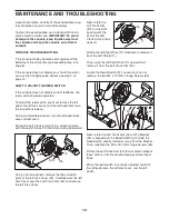
Page 19: ...vertical position with the end of the Left Crank Arm pointing downward Using a flat screwdriver release the tabs on each point of the left Disc Cover 18 Carefully work the left Disc Cover over the Le...

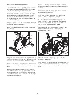
Page 20: ...release the tabs on each point of the right Disc Cover 18 Carefully work the right Disc Cover over the Right Crank Arm 19 and remove the right Disc Cover Note See the drawings on page 19 for more det...

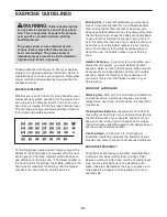
Page 21: ...your goal is to strengthen your cardiovascular system you must perform aerobic exercise which is activity that requires large amounts of oxygen for prolonged periods of time For aerobic exercise adju...

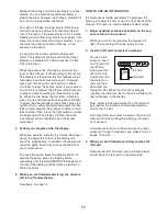
Page 22: ...Bearing 41 2 Snap Ring 42 1 Flywheel 43 2 M8 Washer 44 1 Flywheel Axle 45 1 Idler 46 1 Motor Bracket 47 1 Resistance Motor 48 1 Resistance Disc 49 1 Resistance Arm 50 1 M6 x 70mm Bolt Set 51 1 M6 x 6...

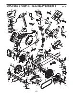
Page 23: ...17 27 19 20 21 22 28 29 31 32 29 32 31 33 34 35 35 36 36 38 39 40 40 41 42 44 45 46 47 48 49 52 53 54 55 55 56 57 58 59 68 68 70 70 71 71 72 72 73 73 74 74 74 75 75 76 76 77 78 79 80 81 82 83 84 85 8...

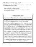
Page 24: ...arranty does not extend to any damage to a product caused by or attributable to freight damage abuse misuse improper or abnormal usage or repairs not provided by an ICON authorized service center to p...

Reviews: