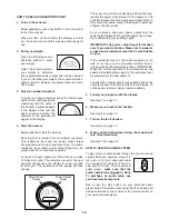
6
82
83
37 83
84
STEP 1
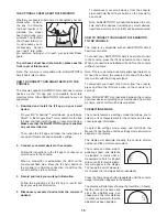
33
22
34
35
90
36
18
84
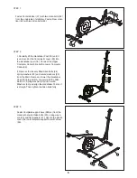
STEP 2
I. Carefully lift the Handlebar Post (18) until it
is vertical. Put the front plastic cover (90) into
the Handlebar post (18). Connect the Upper
Computer Cable (35) and the Lower Computer
Cable (36).
II. Remove the loosely fitted Allen bolts (34),
spring washers (22) and curved washers (33)
from the Main Frame and lower the Handlebar
Post (18) into position. Loosely re-fit the Allen
Bolt (34), Spring washer (22) and Curved
Washers (33) and align the Handlebar Post so it
is straigh. Then tighten the Allen bolts fully
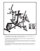
STEP 1
Fasten front stabilizer (37) with two Allen bolts (83)
from the underside of stabilizer. Fasten Rear stabi-
lizer (82) with two Allen bolts (83).
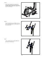
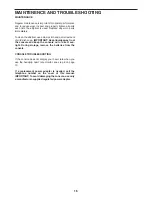
STEP 3
Fasten footplate support bars (28R+L) from the
crank with coated Allen bolts (23), spring wash-
ers (22) and flat washers (21). Secure the plastic
cover (56) onto footplate support bar with screw
(55).
28R
28L
55 56
21 22
59
23


