background image

9

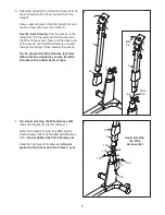
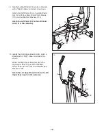
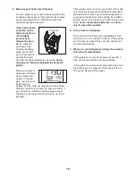
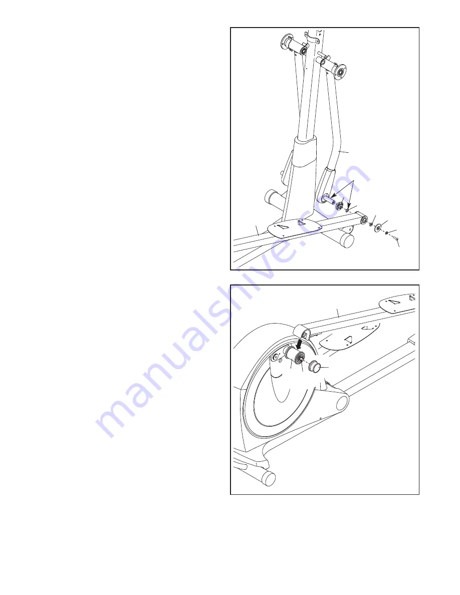
7. Apply grease to the axle on the Right Upper

Body Leg (6) and to a Medium Wave Washer

(119).

Orient a Leg Spacer (55) so that the flat side is

facing away from the elliptical. Slide the Leg

Spacer and the Medium Wave Washer (119)

onto the Right Upper Body Leg (6).

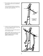
Identify the Right Pedal Arm (12), which is

marked with a “Right” sticker, and orient it as

shown. Slide the Right Pedal Arm onto the

Right Upper Body Leg (6).

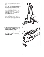
Attach the Right Pedal Arm (12) with an M8 x

23mm Shoulder Patch Screw (121), an M8 x

16mm x 2mm Washer (120), an Axle Cover

(56), and an M8 x 23.5mm x 1mm Washer (110).

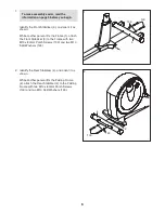
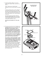
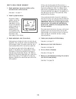
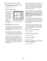
8. Press the Right Pedal Arm (12) onto the right

Adjustment Sleeve (46).

Make sure that the

Right Pedal Arm latches into place.

Tighten an Adjustment Knob (45) onto the right

Adjustment Pin (44).

Repeat step 7 and this step on the other

side of the elliptical.

7

6

55

12

56

120

110

121

119

Grease

8

12

46 44

45

Summary of Contents for 500 ZLE

Page 1: ...PFEVEL95910 0 Serial No Write the serial number in the space above for future reference www iconeurope com QUESTIONS If you have questions or if there are missing parts please contact us Call 08457 089 009 From Ireland 053 92 36102 Website www iconsupport eu E mail Visit www iconsupport eu Write ICON Health Fitness Ltd c o HI Group PLC Express Way Whitwood West Yorkshire WF10 5QJ UK ...

Page 2: ...request a free replacement decal Apply the decal in the location shown Note The decal s may not be shown at actual size TABLE OF CONTENTS WARNING DECAL PLACEMENT 2 IMPORTANT PRECAUTIONS 3 BEFORE YOU BEGIN 4 ASSEMBLY 5 HOW TO USE THE ELLIPTICAL 14 MAINTENANCE AND TROUBLESHOOTING 23 EXERCISE GUIDELINES 25 PART LIST 28 EXPLODED DRAWING 30 ORDERING REPLACEMENT PARTS Back Cover RECYCLING INFORMATION Ba...

Page 3: ... of clearance in the front and rear of the elliptical and 2 ft 0 6 m on each side 6 Inspect and properly tighten all parts regularly Replace any worn parts immediately 7 Keep children under age 12 and pets away from the elliptical at all times 8 The elliptical should not be used by persons weighing more than 286 lbs 130 kg 9 Wear appropriate clothes while exercising do not wear loose clothes that ...

Page 4: ...lection of features designed to make your workouts at home more effective and enjoyable For your benefit read this manual carefully before you use the elliptical If you have questions after reading this manual please see the front cover of this manual To help us assist you note the product model number and serial number before contacting us The model number and the location of the serial number de...

Page 5: ...s the key number of the part from the PART LIST near the end of this manual The number fol lowing the parentheses is the quantity needed for assembly Note If a part is not in the hardware kit check to see if it has been preassembled M8 x 23mm x 2mm Washer 126 2 M8 x 16mm x 2mm Washer 120 2 M10 x 80mm Patch Screw 100 4 Medium Wave Washer 119 2 M8 x 23 5mm x 1mm Washer 110 2 M8 Split Washer 103 14 M...

Page 6: ...tch Screws 100 and two M10 Split Washers 123 2 Identify the Rear Stabilizer 4 and orient it as shown While another person lifts the Folding Frame 2 attach the Rear Stabilizer 4 to the Folding Frame with two M10 x 80mm Patch Screws 100 and two M10 Split Washers 123 1 2 To make assembly easier read the information on page 5 before you begin 3 1 2 4 100 123 123 100 ...

Page 7: ... routed through the Upright Then discard the wire tie Tip To prevent the Wire Harness 60 from falling into the Upright 5 secure the Wire Harness with a rubber band or tape 4 Tip Avoid pinching the Wire Harness 60 Insert the Upright 5 into the Frame 1 Attach the Upright 5 with four M8 x 16mm Patch Screws 102 and four M8 Split Washers 103 Do not tighten the Patch Screws yet Slide the Top Cover 23 do...

Page 8: ... Axle 118 118 48 5 Grease Grease 6 6 Identify the Right and Left Upper Body Legs 6 7 which are marked with Right and Left stick ers and orient them as shown Slide the Right and Left Upper Body Legs 6 7 onto the Upright Axle 48 Tighten two M8 x 16mm Patch Screws 102 with M8 x 23mm x 2mm Washers 126 into the Upright Axle 48 at the same time Firmly tighten the Patch Screws 102 102 126 126 48 6 7 Avoi...

Page 9: ...orient it as shown Slide the Right Pedal Arm onto the Right Upper Body Leg 6 Attach the Right Pedal Arm 12 with an M8 x 23mm Shoulder Patch Screw 121 an M8 x 16mm x 2mm Washer 120 an Axle Cover 56 and an M8 x 23 5mm x 1mm Washer 110 8 Press the Right Pedal Arm 12 onto the right Adjustment Sleeve 46 Make sure that the Right Pedal Arm latches into place Tighten an Adjustment Knob 45 onto the right A...

Page 10: ...h the Left Pedal 15 to the Left Pedal Arm 13 in the same way 12 14 13 15 111 111 112 112 10 8 6 7 9 102 103 103 10 Identify the Right Upper Body Arm 8 which is marked with a Right sticker and orient it as shown Attach the Right Upper Body Arm 8 to the Right Upper Body Leg 6 with three M8 x 16mm Patch Screws 102 and three M8 Split Washers 103 Attach the Left Upper Body Arm 9 to the Left Upper Body ...

Page 11: ...ed IMPORTANT If the Console has been exposed to cold temperatures allow it to warm to room temperature before inserting batteries Otherwise you may damage the console displays or other electronic compo nents Remove the screw remove the battery cover insert batteries into the battery compart ment and reattach the battery cover Make sure to orient the batteries as shown by the dia gram inside the ba...

Page 12: ...res 34 Insert the excess wire into the Console 33 Tip Avoid pinching the wires Attach the Console 33 to the Upright 5 with four M4 x 16mm Screws 93 13 14 14 Attach the Rear Upright Cover 24 to the Upright 5 with two M4 x 16mm Screws 93 and an M4 x 19mm Flat Head Screw 117 33 34 60 93 93 117 24 5 5 Console Wires Avoid pinching the wires ...

Page 13: ... 16 Identify the Right Rear and Front Leg Covers 29 30 which are marked with Right stickers Attach the Right Rear Leg Cover 29 to the Right Upper Body Leg 6 with three M4 x 16mm Screws 93 Attach the Right Front Leg Cover 30 around the Right Upper Body Leg 6 by pressing the tabs on the Right Front Leg Cover into the Right Rear Leg Cover 29 Attach the Left Rear and Front Leg Covers 31 32 in the same...

Page 14: ...PTICAL To move the elliptical first fold it as described at the left Next stand in front of the elliptical hold the upright and place one foot against one of the wheels Pull the upright until the elliptical rolls on the front wheels Carefully move the elliptical to the desired position and then lower it HOW TO ADJUST THE STRIDE LENGTH OF THE ELLIPTICAL To adjust the stride length of the elliptical...

Page 15: ...r for variety you can turn the crank arms in the opposite direction To dismount the elliptical wait until the pedals come to a complete stop Note The elliptical does not have a freewheel the pedals will continue to move until the flywheel stops When the pedals are stationary step off the highest pedal first Then step off the low est pedal HOW TO ELIMINATE FLEXING IN THE CENTER OF THE ELLIPTICAL If...

Page 16: ...kout system which enables the console to accept iFit cards containing workouts designed to help you achieve specific fitness goals For example lose unwanted pounds with the 8 week Weight Loss workout iFit workouts control the resistance of the pedals while the voice of a personal trainer coaches you through your workouts iFit cards are available separately To purchase iFit cards go to www iFit com...

Page 17: ...splay The lower right display can show your pedaling speed in revolutions per minute rpm and the approximate number of calories that you have burned Note When a calorie goal workout is selected the display will count down the number of calories to be burned The display also shows your heart rate when you use the handgrip pulse sensor or the optional chest pulse sensor see step 5 on page 18 The upp...

Page 18: ...inue to hold the handgrip pulse sensor the display will show your heart rate for up to 30 seconds If the display does not show your heart rate make sure that your hands are positioned as described Be careful not to move your hands excessively or to squeeze the metal contacts tightly For optimal performance clean the metal contacts using a soft cloth never use alcohol abrasives or chemi cals to cle...

Page 19: ...l for the cur rent segment At the end of each segment of the workout a series of tones will sound and the next segment of the profile will begin to flash If a different resis tance level is programmed for the next segment the resistance level will appear in the display for a few seconds to alert you The resistance of the pedals will then change If the resistance level for the current segment is to...

Page 20: ... segment At the end of each segment of the workout a series of tones will sound and the next segment of the profile will begin to flash If a different resis tance level is programmed for the next segment the resistance level will appear in the display for a few seconds to alert you The resistance of the pedals will then change If the resistance level for the current segment is too high or too low ...

Page 21: ...d decrease buttons next to the iFit slot A moment after you select a workout the voice of a personal trainer will begin guiding you through your workout iFit workouts function in the same way as preset workouts To use the workout see steps 3 to 7 on page 19 3 When you are finished exercising remove the iFit card Remove the iFit card when you are finished exer cising Store the iFit card in a secure...

Page 22: ... pedaling The OFF option turns the backlight off The upper display will show the cur rently selected backlight option Press the Digital Resistance decrease button repeatedly to select the desired back light option 3 View console usage information if desired The lower left display will show the total number of hours that the console has been used since the elliptical was purchased 4 Exit the user m...

Page 23: ...ep 5 on page 18 HOW TO ADJUST THE REED SWITCH If the console does not display correct feedback the reed switch should be adjusted To adjust the reed switch you must first remove the Top Shield 20 Using a flat screwdriver release the tabs on the front and rear of the Top Shield and then remove the Top Shield Next locate the Reed Switch 69 Loosen but do not remove the M4 x 16mm Screw 93 Next rotate ...

Page 24: ...abs on the front and rear of the Top Shield 20 and then remove the Top Shield Next remove the M4 x 16mm Screws 93 and the M4 x 42mm Screws 124 from the Right and Left Shields 18 19 Make sure to note which size of Screw you remove from each hole Then gently remove the Left Shield Loosen the Pivot Screw 97 Then tighten the Belt Adjustment Screw 85 until the Drive Belt 38 is tight When the Drive Belt...

Page 25: ...f your goal is to strengthen your cardiovascular system you must perform aerobic exercise which is activity that requires large amounts of oxygen for prolonged periods of time For aerobic exercise adjust the intensity of your exercise until your heart rate is near the highest number in your training zone WORKOUT GUIDELINES Warming Up Start with 5 to 10 minutes of stretching and light exercise A wa...

Page 26: ...illes Stretch With one leg in front of the other reach forward and place your hands against a wall Keep your back leg straight and your back foot flat on the floor Bend your front leg lean forward and move your hips toward the wall Hold for 15 counts then relax Repeat 3 times for each leg To cause further stretching of the achilles tendons bend your back leg as well Stretches Calves achilles tendo...

Page 27: ...27 NOTES ...

Page 28: ...rm 44 2 Adjustment Pin 45 2 Adjustment Knob 46 2 Adjustment Sleeve 47 4 Sleeve Bushing 48 1 Upright Axle 49 2 Latch Housing 50 2 Latch 51 2 Latch Spring 52 2 Latch Insert 53 2 Adjustment Arm Spring 54 4 Leg Bearing Assembly 55 2 Leg Spacer 56 2 Axle Cover 57 2 Upright Bushing 58 4 Pedal Arm Bushing 59 1 Audio Cable 60 1 Wire Harness 61 1 Flywheel 62 1 6000ZZ Bearing 63 1 Frame Axle 64 2 Frame Bush...

Page 29: ... 25mm Button Screw 108 2 M10 x 32mm Washer 109 2 M8 x 16mm Button Screw 110 4 M8 x 23 5mm x 1mm Washer 111 8 M6 x 12mm Patch Screw 112 8 M6 Split Washer 113 2 M8 x 18mm Button Screw 114 2 M8 x 32mm Washer 115 2 Large Wave Washer 116 2 Large Snap Ring 117 5 M4 x 19mm Flat Head Screw 118 2 Small Wave Washer 119 2 Medium Wave Washer 120 2 M8 x 16mm x 2mm Washer 121 2 M8 x 23mm Shoulder Patch Screw 12...

Page 30: ...12 45 46 47 47 116 50 51 52 49 93 93 44 53 115 114 113 43 47 46 116 45 111 112 112 12 14 47 58 58 56 120 121 125 55 28 27 125 28 27 55 5 24 26 6 29 8 102 54 126 102 93 102 10 30 34 93 59 25 35 93 117 93 93 54 57 118 57 118 48 54 54 102 102 32 34 93 33 93 126 102 11 31 7 103 103 103 103 103 103 119 110 119 110 103 103 127 106 127 106 ...

Page 31: ...41 110 122 109 65 109 16 66 2 4 100 38 37 20 75 75 86 86 87 76 73 74 72 40 86 17 16 93 124 93 93 124 93 60 18 19 23 62 61 22 1 64 108 107 64 63 108 107 93 21 17 39 86 86 102 103 102 103 102 103 102 37 37 3 100 36 36 105 104 104 124 124 123 123 86 101 93 95 EXPLODED DRAWING B Model No PFEVEL95910 0 R0410A ...

Page 32: ...art s see the PART LIST and the EXPLODED DRAWING near the end of this manual RECYCLING INFORMATION This electronic product must not be disposed of in municipal waste To pre serve the environment this product must be recycled after its useful life as required by law Please use recycling facilities that are authorized to collect this type of waste in your area In doing so you will help to conserve n...

Reviews: