


7
10
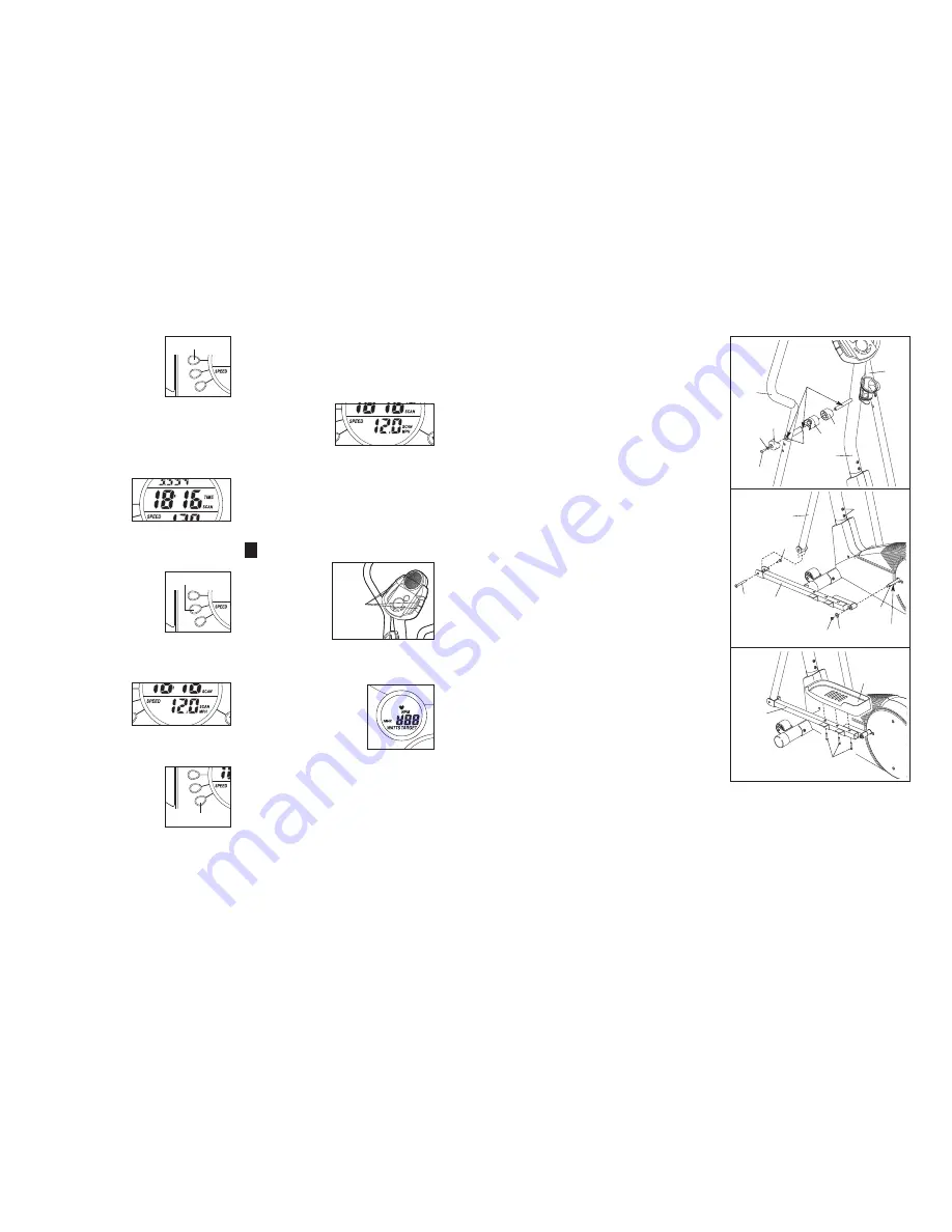
8. Apply a generous amount of grease to the axle on
the left Disc Crossbar (16). Slide the Left Pedal Arm
(11) onto the axle and attach it with an M8.5 Washer
(35) and an M8 Nylon Locknut (38).
Insert the left Handlebar Arm (5) into the bracket on
the end of the Left Pedal Arm (11), and attach it with
a Pedal Arm Bolt Set (40).
Repeat this step to attach the right Pedal Arm (not
shown).
See step 6. Tighten the M8 x 45mm Button Bolts (50)
in the Handlebar Arms (5).
Tighten the two M10 x 74mm Button Bolts (27).
8
5
11
35
38
27
40
40
Grease
16
7. Apply a generous amount of the included grease to
the left axle on the Upright (2) and inside of the two
small Handlebar Bushings (49) in the Left Handlebar
(6).
Slide a Frame Spacer (48), a Handlebar Spacer (47),
the Left Handlebar (6), and a Handlebar Cap (46) onto
the left axle on the Upright (2) as shown. Slide an M10
Washer (55) onto an M8 x 19mm Shoulder Screw (56),
and tighten the Shoulder Screw into the axle.
Attach the Right Handlebar (8) in the same way.
7
48
2
46
8
6
55
56
47
49
Grease
10.
Make sure that all parts of the elliptical trainer are properly tightened. Place a mat under the elliptical
trainer to protect the floor or carpet from damage.
9. Find the Left Pedal (13), which has a ridge on the
right side. Attach the Left Pedal to the Left Pedal Arm
(11) with three M4 x 19mm Flange Screws (36) as
shown.
Attach the Right Pedal to the Right Pedal Arm (not
shown) in the same way.
11
9
13
36
To view only the distance
you have pedaled or the
number of calories or fat
calories you have burned,
press the upper button on
the left side of the large
display until only the word
DISTANCE, CALORIES,
or FAT CALS appears in the upper section of the
large display; make sure that the word SCAN
does not appear. To again view the distance you
have pedaled and the numbers of calories and fat
calories you have burned, press the upper button
until the word SCAN reappears.
The centre of
the large dis-
play will show
the elapsed time
and your current
pace (pace is
shown in minutes per mile in this section of the
large display). The display will change from one
number to the other every few seconds.
To view only the elapsed
time or your pace, press
the centre button on the
left side of the large dis-
play until only the word
TIME or PACE appears;
make sure that the word
SCAN does not appear. To
again view both the elapsed time and your pace,
press the centre button until the word SCAN
reappears.
The lower sec-
tion of the large
display will show
your pedaling
speed and the
resistance level.
The display will change from one number to the
other every few seconds.
To view only your pedaling
speed or the resistance
level, press the lower but-
ton on the left side of the
large display until only the
word SPEED or RESIS-
TANCE appears; make
sure that the word SCAN does not appear. To
again view both your pedaling speed and the
resistance level, press the lower button until the
word SCAN reappears.
To reset the displays, press the On/Reset button.
Note: The con-
sole can show
speed and dis-
tance in either
miles or kilome-
ters. The letters
MPH or KM/H will appear in the lower section of
the large display to show which unit of measure-
ment is selected. To change the unit of measure-
ment, hold down the On/Reset button for about six
seconds. Note: When the button is held down, the
fan will turn on for a moment. When the batteries
are replaced, it may be necessary to reselect the
desired unit of measurement.
Measure your heart rate if desired.
If there are thin
sheets of plas-
tic on the metal
contacts on the
handgrips, peel
off the plastic.
To use the hand-
grip pulse sen-
sor, hold the
handgrips with
your palms resting against the metal contacts.
Avoid moving your hands.
When your pulse is
detected, the heart-
shaped indicator in the
small display will flash
each time your heart
beats. After a moment,
two dashes (– –) will
appear and then your
heart rate will be shown.
For the most accurate heart rate reading, continue
to hold the handgrips for about 30 seconds.
4
Upper Button
Centre Button
Lower Button
Metal
Contacts


