background image

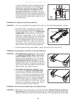
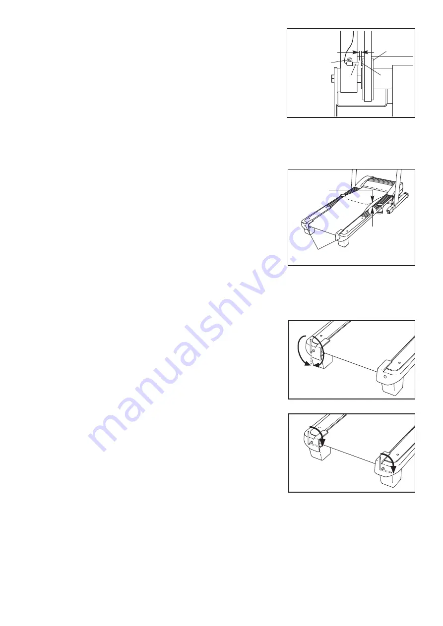
Locate the Reed Switch (63) and the Magnet (46) on

the left side of the Pulley (47). Turn the Pulley until

the Magnet is aligned with the Reed Switch.

Make

sure that the gap between the Magnet and the

Reed Switch is about 1/8 in. (3 mm).

If necessary,

loosen the Screw (7), move the Reed Switch slightly,

and then retighten the Screw. Reattach the Hood, and

run the treadmill for a few minutes to check for a cor-

rect speed reading.

PROBLEM: The walking belt slows when walked on

SOLUTION:

a. Use only a single-outlet surge suppressor that meets all of the specifications described on page 9.

b. If the walking belt is overtightened, treadmill perfor-

mance may decrease and the walking belt may be-

come damaged. Remove the key and

UNPLUG THE

POWER CORD

. Using the hex key, turn both rear

roller bolts counterclockwise, 1/4 of a turn. When the

walking belt is properly tightened, you should be able

to lift each edge of the walking belt 2 to 3 in. (5 to 7

cm) off the walking platform. Be careful to keep the

walking belt centered. Then, plug in the power cord,

insert the key, and run the treadmill for a few minutes.

Repeat until the walking belt is properly tightened.

c. If the walking belt still slows when walked on, please see the front cover of this manual.

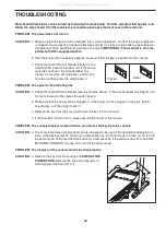
PROBLEM: The walking belt is off-center or slips when walked on

SOLUTION:

a.

If the walking belt is off-center,

first remove the key

and

UNPLUG THE POWER CORD

.

If the walking

belt has shifted to the left,

use the hex key to turn

the left rear roller bolt clockwise 1/2 of a turn;

if the

walking belt has shifted to the right,

turn the bolt

counterclockwise 1/2 of a turn. Be careful not to over-

tighten the walking belt. Then, plug in the power cord,

insert the key, and run the treadmill for a few minutes.

Repeat until the walking belt is centered.

b.

If the walking belt slips when walked on,

first re-

move the key and

UNPLUG THE POWER CORD

.

Using the hex key, turn both rear roller bolts clock-

wise, 1/4 of a turn. When the walking belt is correctly

tightened, you should be able to lift each side of the

walking belt 2 to 3 in. (5 to 7 cm) off the walking plat-

form. Be careful to keep the walking belt centered.

Then, plug in the power cord, insert the key, and care-

fully walk on the treadmill for a few minutes. Repeat

until the walking belt is properly tightened.

PROBLEM: The incline of the treadmill does not change correctly

SOLUTION:

a. With the key in the console, press one of the Incline buttons.

While the incline is changing, re-

move the key.

After a few seconds, re-insert the key. The treadmill will automatically rise to the

maximum incline level and then return to the minimum level. This will recalibrate the incline system.

b

a

Rear Roller Bolts

2–3 in.

b

Top

View

19

46

7

63

1/8 in.

47

All manuals and user guides at all-guides.com

Summary of Contents for 560 Crosstrainer

Page 1: ...we are com mitted to providing complete cus tomer satisfaction If you have questions or if parts are damaged or missing DO NOT CONTACT THE STORE please contact Customer Care IMPORTANT You must note t...

Page 2: ...PLACEMENT PARTS Back Cover LIMITED WARRANTY Back Cover 2 PROFORM is a registered trademark of ICON IP Inc This drawing shows the locations of the warning de cals If a decal is missing or illegible cal...

Page 3: ...Use only a single outlet surge suppressor that meets all of the specifications described on page 9 To purchase a surge suppressor see your local PROFORM dealer or call the telephone number on the fron...

Page 4: ...ed they may fall off the console causing the user to trip 23 When folding or moving the treadmill make sure that the storage latch is holding the frame securely in the storage position 24 Never insert...

Page 5: ...l To help us assist you note the product model number and serial number before contacting us The model number and the location of the serial number decal are shown on the front cover of this manual To...

Page 6: ...needed for assembly Note If a part is not in the parts bag check to see if it has been preassembled To avoid damaging plastic parts do not use power tools for assembly Extra hardware may be included...

Page 7: ...not fully fold the treadmill until it is completely assembled Insert the other Extension Leg 89 into the base of the Uprights 84 Hold an Extension Leg Nut 67 in the bottom of the Extension Leg and thr...

Page 8: ...enna 3 76 Wire Small Screws 5 Attach the Latch Housing 73 to the left Upright 84 with two Screws 3 start both Screws and then tighten them Note Make sure that the large hole in the Latch Housing is on...

Page 9: ...ounding provides a path of least resistance for electric current to reduce the risk of elec tric shock This product is equipped with a cord having an equipment grounding conductor and a grounding plug...

Page 10: ...em while toning and strengthening your muscles The cross training programs control the speed and incline of the treadmill and prompt you to perform a variety of strength exercises during your workouts...

Page 11: ...s in this section refer to miles HOW TO USE THE MANUAL MODE Insert the key into the console See HOW TO TURN ON THE POWER above Enter your weight if desired If you enter your weight into the console th...

Page 12: ...Note If you use the handgrip pulse sensor and the optional chest pulse sensor at the same time the console will not display your heart rate accurately See page 16 for information about the optional ch...

Page 13: ...cline setting are programmed for each segment Note The same speed setting and or incline setting may be programmed for consecutive segments During the workout the profile will show your progress The f...

Page 14: ...segments One speed setting and one incline set ting are programmed for each segment Note The same speed setting and or incline setting may be programmed for consecutive segments During other segments...

Page 15: ...hen performing dumbbell rows perform half the repetitions with your right arm and half the repeti tions with your left arm The strength exercises re quire the use of dumbbells and an inflatable exer c...

Page 16: ...t has moved In addition an E for English miles or an M for metric kilometers will appear in the lower left part of the dis play To change the unit of measurement press the Quick Speed increase button...

Page 17: ...irect sun light Do not leave the treadmill in the storage position in temperatures above 85 F 30 C HOW TO MOVE THE TREADMILL Before moving the treadmill convert it to the storage position as described...

Page 18: ...ing use SOLUTION a Check the reset off circuit breaker see the drawing above If the circuit breaker has tripped wait for five minutes and then press the switch back in b Make sure that the power cord...

Page 19: ...s when walked on SOLUTION a If the walking belt is off center first remove the key and UNPLUG THE POWER CORD If the walking belt has shifted to the left use the hex key to turn the left rear roller bo...

Page 20: ...engthen your cardiovascular system you must perform aerobic exer cise which is activity that requires large amounts of oxygen for prolonged periods of time For aerobic ex ercise adjust the intensity o...

Page 21: ...f the other reach forward and place your hands against a wall Keep your back leg straight and your back foot flat on the floor Bend your front leg lean forward and move your hips toward the wall Hold...

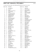
Page 22: ...nt Roller Pulley 48 1 Walking Belt 49 1 Walking Platform 50 1 Incline Motor Controller Wire 51 1 Rear Roller 52 1 Left Rear Endcap 53 2 Rear Roller Bolt 54 1 Right Rear Endcap 55 1 Hex Key 56 1 Inclin...

Page 23: ...107 4 Crossbar Star Washer 108 3 Hood Clip 109 1 Crossbar 110 1 Fan with Cover 111 1 Console Ground Wire 10 Red Wire M F 12 Blue Wire 2F 8 Black Wire M F 12 Blue Wire M F User s Manual Note Specifica...

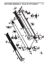
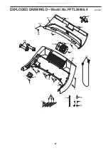
Page 24: ...7 46 1 5 5 5 5 9 51 52 48 3 55 3 54 103 12 11 58 17 10 15 60 60 104 53 66 105 53 66 105 70 2 6 2 6 12 99 3 70 2 2 90 90 101 103 2 6 2 6 33 24 EXPLODED DRAWING A Model No PFTL59906 4 R1108A All manuals...

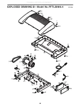
Page 25: ...33 38 39 95 28 32 32 36 18 87 25 22 27 30 23 26 19 24 22 25 30 42 7 7 61 40 72 33 4 13 43 45 50 91 28 7 108 108 108 33 25 EXPLODED DRAWING B Model No PFTL59906 4 R1108A All manuals and user guides at...

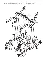
Page 26: ...80 67 89 81 78 80 67 89 81 78 44 31 32 65 35 65 77 62 3 14 14 83 93 94 95 96 97 3 3 3 3 3 3 77 102 33 57 20 62 20 106 106 3 64 64 3 3 107 107 8 8 32 26 EXPLODED DRAWING C Model No PFTL59906 4 R1108A...

Page 27: ...3 76 79 75 7 74 71 34 85 3 3 3 91 37 33 100 98 3 3 3 3 110 7 111 3 3 3 3 27 EXPLODED DRAWING D Model No PFTL59906 4 R1108A All manuals and user guides at all guides com...

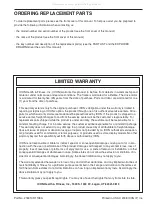
Page 28: ...sponsible for a minimal handling charge For in home service the customer will be responsible for a minimal trip charge This warranty does not extend to any damage to a product caused by or attributabl...

Reviews: