background image

14

HOW TO TURN ON THE POWER

IMPORTANT: If the treadmill has been exposed to

cold temperatures, allow it to warm to room tem-

perature before turning on the power. If you do not

do this, you may damage the console displays or

other electrical components.

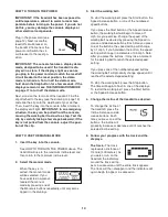
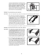
Plug in the power cord (see

page 12). Next, locate the

reset/off circuit breaker on

the treadmill frame near the

power cord. Switch the cir-

cuit breaker to the reset po-

sition.

IMPORTANT: The console features a display demo

mode, designed to be used if the treadmill is dis-

played in a store. If the displays light as soon as

you plug in the power cord and switch the reset/off

circuit breaker to the reset position, the demo

mode is turned on. To turn off the demo mode,

hold down the Stop button for a few seconds. If the

displays remain lit, see THE INFORMATION MODE

on page 17 to turn off the demo mode.

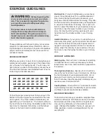
Next, stand on the foot rails of the treadmill. Find the

clip attached to the key (see the drawing on page 13)

and slide the clip onto the waistband of your clothes.

Then, insert the key into the console. After a moment,

the displays will light.

IMPORTANT: In an emergency

situation, the key can be pulled from the console,

causing the walking belt to slow to a stop. Test the

clip by carefully taking a few steps backward; if the

key is not pulled from the console, adjust the posi-

tion of the clip.

HOW TO USE THE MANUAL MODE

1. Insert the key into the console.

See HOW TO TURN ON THE POWER above. The

treadmill will rise to the maximum incline level and

then return to the minimum incline level.

2. Select the manual mode.

When the key is in-

serted, the manual mode

will be selected. If you

have selected a workout,

reselect the manual

mode by pressing one of

the Workouts buttons repeatedly until only zeros

appear in the displays.

3. Start the walking belt.

To start the walking belt, press the Start button, the

Speed increase button, or one of the numbered

speed buttons.
If you press the Start button or the Speed increase

button, the walking belt will begin to move at 1

mph. As you exercise, change the speed of the

walking belt as desired by pressing the Speed in-

crease and decrease buttons. Each time you press

one of the buttons, the speed setting will change

by 0.1 mph; if you hold down the button, the speed

setting will change in increments of 0.5 mph. Note:

After you press the buttons, it may take a moment

for the walking belt to reach the selected speed

setting.

If you press one of the numbered speed buttons,

the walking belt will gradually change speed until it

reaches the selected speed setting.

To stop the walking belt, press the Stop button.

The time will begin to flash in one of the displays.

To restart the walking belt, press the Start button

or the Speed increase button.

4. Change the incline of the treadmill as desired.

To change the incline of

the treadmill, press the

Incline increase and de-

crease buttons. Each

time you press one of the

buttons, the incline will

gradually increase or decrease until it reaches the

selected incline setting.

5. Follow your progress with the track and the

displays.

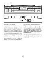
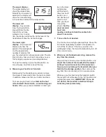
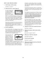
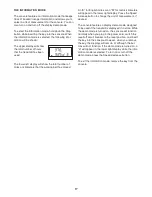
The track

—The track

represents a distance of

1/4 mile (400 meters). As

you walk or run on the

treadmill, the indicators

around the track will ap-

pear in succession until the entire track appears.

The track will then disappear and the indicators will

again begin to appear in succession.

Reset

Summary of Contents for 6.0 ZT

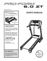
Page 1: ...ference Serial Number Decal USER S MANUAL QUESTIONS If you have questions or if parts are damaged or missing DO NOT CON TACT THE STORE please contact Customer Care IMPORTANT Please register this produ...

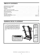
Page 2: ...D DRAWING 24 ORDERING REPLACEMENT PARTS Back Cover LIMITED WARRANTY Back Cover 2 PROFORM is a registered trademark of ICON IP Inc WARNING DECAL PLACEMENT This drawing shows the locations of the warnin...

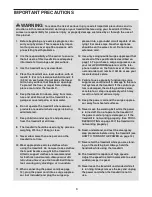
Page 3: ...nce should be on the same circuit Do not use an extension cord 12 Use only a single outlet surge suppressor that meets all of the specifications described on page 12 To purchase a surge suppressor see...

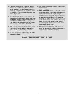
Page 4: ...orage latch is holding the frame securely in the storage position 23 Inspect and properly tighten all parts of the treadmill regularly 24 Never insert any object into any opening on the treadmill 25 D...

Page 5: ...have questions after read ing this manual please see the front cover of this man ual To help us assist you note the product model number and serial number before contacting us The model number and the...

Page 6: ...the drawings below to identify the assembly hardware The number in parentheses below each drawing is the key number of the part from the PART LIST near the end of this manual The number after the par...

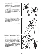
Page 7: ...ghten the Bolts yet 48 31 39 39 5 Latch Holes 2 4 Raise the Uprights 31 36 so that the Base 48 is flat on the floor and positioned as shown Cut the tie holding the Upright Wire 28 in a bun dle See the...

Page 8: ...Frame with a 3 8 x 2 1 2 Bolt 32 a 3 8 Flat Washer 33 and a 3 8 Nut 47 do not tighten the Bolt yet 5 36 32 32 34 34 33 47 47 59 33 59 Outer Side 34 36 6 See the left inset drawing Identify the outer...

Page 9: ...Base to the right Handrail with a 8 x 1 2 Ground Screw 27 Connect the wire harness on the Console Base 26 to the Upright Wire 28 as shown in the inset drawing If the connectors are oriented correctly...

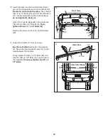
Page 10: ...32 74 74 31 View from Above Side View 11 5 10 22 10 Insert the wires into the Console Base 26 as you set the Console Base on the Handrails 18 Be careful not to pinch the wires Next thread two 1 4 x 1...

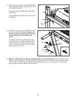
Page 11: ...Attach the ground wire on the Upright Wire 28 to the indicated hole in the Base 48 with a 8 x 1 2 Ground Screw 27 Press the indicated Grommet 86 into the Right Upright 36 Raise the Right Upright 36 a...

Page 12: ...eak down grounding provides a path of least resistance for electric current to reduce the risk of elec tric shock This product is equipped with a cord having an equipment grounding conductor and a gro...

Page 13: ...ne of the treadmill as it guides you through an effective exercise session To turn on the power see page 14 To use the man ual mode see page 14 To use a preset workout see page 16 To use the informati...

Page 14: ...ey is in serted the manual mode will be selected If you have selected a workout reselect the manual mode by pressing one of the Workouts buttons repeatedly until only zeros appear in the displays 3 St...

Page 15: ...on the foot rails and hold the contacts avoid moving your hands When your pulse is detected a heart sym bol in the lower right display will flash each time your heart beats one or two dashes will app...

Page 16: ...und and the next segment of the profile will begin to flash If a different speed or in cline setting is programmed for the next segment the speed or incline setting will flash in the display to alert...

Page 17: ...for English miles or an M for metric kilometers will appear in the lower right display Press the Speed increase button to change the unit of measurement if desired The console features a display demo...

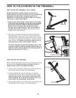
Page 18: ...he latch pin and then slowly re lease the latch knob Make sure that the latch pin is fully inserted into the center of the platform cushion To protect the floor or carpet from damage place a mat under...

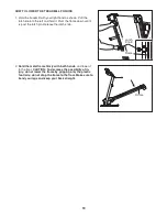
Page 19: ...n until it is past the latch pin Release the latch knob 2 Hold the metal frame firmly with both hands and lower it to the floor CAUTION To decrease the possibility of in jury do not lower the frame by...

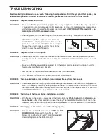
Page 20: ...switch back in b Make sure that the power cord is plugged in If the power cord is plugged in unplug it wait for five minutes and then plug it back in c Remove the key from the console Reinsert the key...

Page 21: ...e treadmill for a few minutes Repeat until the walking belt is properly tightened c If the walking belt still slows when walked on please see the front cover of this manual PROBLEM The walking belt is...

Page 22: ...our goal is to strengthen your cardiovascular system you must perform aerobic exer cise which is activity that requires large amounts of oxygen for prolonged periods of time For aerobic ex ercise adju...

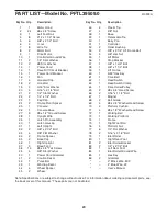
Page 23: ...se Bar 43 1 Warning Decal 44 4 Wheel Spacer 45 2 Wheel 46 3 Plastic Tie 47 4 3 8 Nut 48 1 Base 49 1 Releasable Tie 50 1 Belly Pan 51 1 Controller 52 2 Roller Bushing 53 2 3 8 x 2 1 4 Lift Frame Bolt 5...

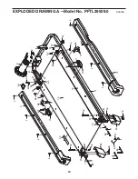
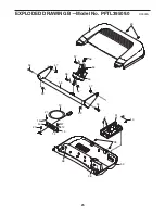
Page 24: ...66 24 64 66 72 73 4 4 3 71 68 70 69 4 4 78 78 27 76 83 38 82 85 84 27 82 11 79 80 38 76 4 4 74 75 4 68 4 69 70 63 24 71 76 76 67 43 81 81 60 27 52 52 77 77 77 11 77 27 24 EXPLODED DRAWING A Model No...

Page 25: ...65 1 50 51 2 38 38 38 53 47 59 47 53 58 57 56 54 54 55 13 27 27 27 12 12 14 33 33 15 40 10 25 EXPLODED DRAWING B Model No PFTL39509 0 R0909A...

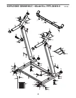
Page 26: ...21 22 28 2 21 22 20 19 17 17 18 31 35 34 37 38 33 32 35 34 32 33 48 39 5 39 5 37 38 28 27 37 38 45 5 44 44 47 37 38 47 44 45 44 5 2 29 41 41 2 2 2 2 42 49 7 38 2 2 46 6 6 93 EXPLODED DRAWING C Model...

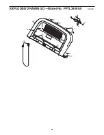
Page 27: ...2 2 16 25 23 26 2 2 2 2 2 2 27 27 EXPLODED DRAWING D Model No PFTL39509 0 R0909A...

Page 28: ...ranty does not extend to any damage to a product caused by or attributable to freight damage abuse misuse improper or abnormal usage or repairs not provided by an ICON authorized service cen ter to pr...

Reviews: