background image

8

25

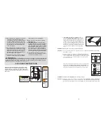
HOW TO FOLD AND MOVE THE TREADMILL

HOW TO FOLD THE TREADMILL FOR STORAGE

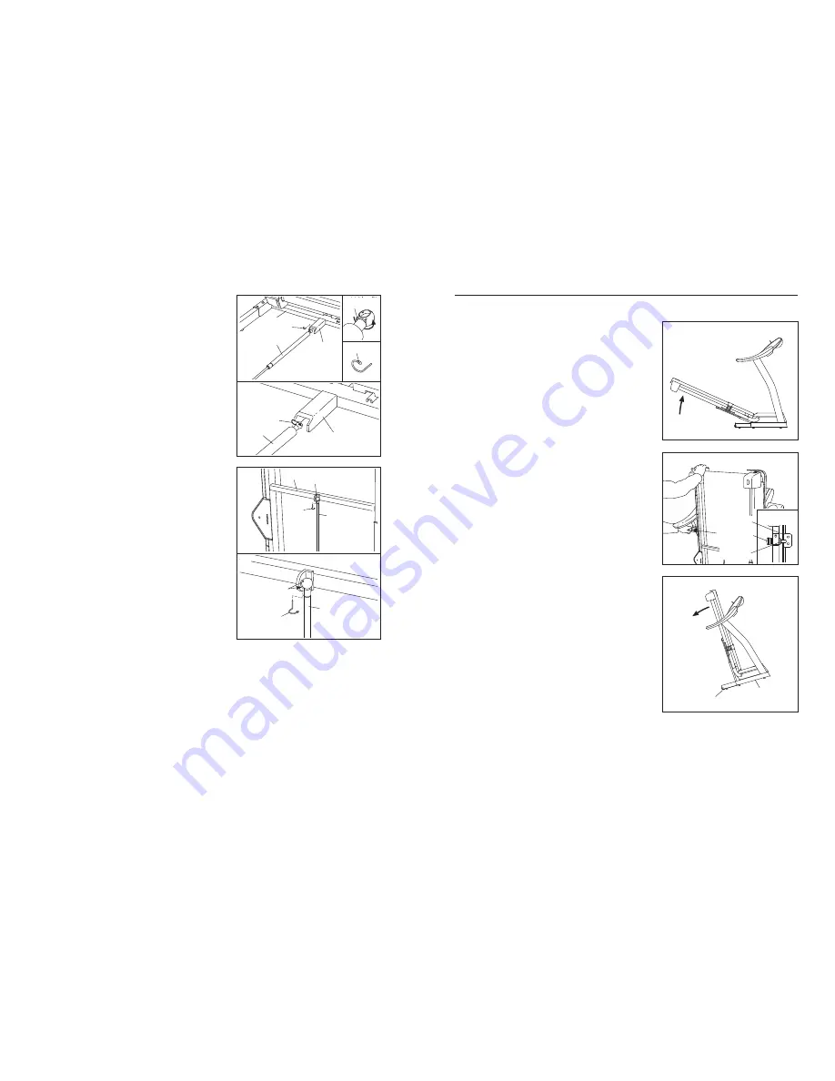
Before folding the treadmill, adjust the incline to the 
lowest position. If this is not done, the treadmill may be-
come permanently damaged. Next, unplug the power cord.
CAUTION: You must be able to safely lift 45 pounds (20 kg)
to raise, lower, or move the treadmill.

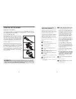
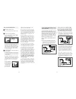
1.  Hold the treadmill frame with your hands in the location

shown by the arrow at the right. 

To decrease the possibility

of injury, bend your legs and keep your back straight. As
you raise the frame, make sure to lift with your legs
rather than your back.

Raise the frame about halfway to the

vertical position. 

2. Move your right hand to the position shown and hold the

treadmill firmly. Using your left hand, pull the latch knob to
the left and hold it. Raise the frame until the catch passes the
latch pin. Slowly release the latch knob. 

Make sure that the

catch is resting against the latch pin. 

To protect the floor or carpet from damage, place a mat
under the treadmill. Keep the treadmill out of direct sun-
light. Do not leave the treadmill in the storage position in
temperatures above 85° Fahrenheit.

HOW TO MOVE THE TREADMILL 

Before moving the treadmill, convert the treadmill to the storage
position as described above. 

Make sure that the catch is rest-

ing against the latch pin.  

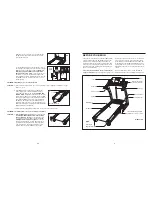
1.  Hold the upper ends of the handrails. Place one foot against

one of the wheels.

2.  Tilt the treadmill back until it rolls freely on the front wheels.

Carefully move the treadmill to the desired location. 

To re-

duce the risk of injury, use extreme caution whilst mov-
ing the treadmill. Do not move the treadmill over an un-
even surface.

3.  Place one foot against one of the wheels, and carefully lower

the treadmill until it is resting in the storage position.

Engaged

Catch

Latch Knob

Latch Pin

Base

Wheel

7.

Make sure that all parts are properly tightened before you use the treadmill.

If there are sheets of clear

plastic on the treadmill decals, remove the plastic. To protect the floor or carpet, place a mat under the tread-
mill. Note: Extra hardware may be included. Keep the included hex key in a secure place; the large hex key is
used to adjust the walking belt (see page 28).  

5. Place the treadmill in the storage position (see HOW TO

FOLD AND MOVE THE TREADMILL on page 25). 

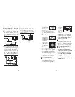
Next, place the cylinder end of the Shock (108) near the
bracket on the base of the Uprights (84). 

See the two small inset drawings. Using your fingernail
or the end of a screwdriver, press on the end of the
Shock Pin (112) to loosen it from the Shock (108). Next,
rotate the Shock Pin and pull it out of the Shock. 

Be

careful to avoid losing the Shock Pin.

See drawing 5a. Press the cylinder end of the Shock
(108) onto the ball on the bracket. Next, insert the end of
the Shock Pin (112) through two of the small holes in the
end of the Shock. Then, rotate the Shock Pin until it clips
onto the Shock.

108

112

108

112

5

5a

84

Bracket

Bracket

6. Raise the Shock (108) to a vertical position. Remove the

Shock Pin (112) from the raised end of the Shock as de-
scribed in step 5. If necessary, rotate the Shock to align
the end of the Shock with the ball on the bracket on the
Frame (58).

Plug in the power cord as described on page 10. Turn on
the power as described on page 12. Next, press the
Incline increase and decrease buttons until the ball on
the bracket is aligned with end of the Shock (108). Then,
press the end of the Shock onto the ball. Note: It may be
necessary to press the end of the Shock onto the ball
whilst the Frame is moving.

See drawing 6a. Insert the Shock Pin (112) into the two
indicated small holes in the end of the Shock (108).
Then, rotate the Shock Pin until it clips onto the Shock.
Note: Extra Shock Clips are included.

Press the Incline decrease button until the treadmill is at
the lowest incline level. Then, unplug the power cord. 

112

108

Holes

112

108

6

6a

58

Bracket

112

112

Summary of Contents for 660VX PETL62705.0

Page 1: ...he UK 44 113 387 7133 Fax 44 113 387 7125 To help us assist you please be prepared to give the following information the MODEL NUMBER of the product PETL62705 0 the NAME of the product PROFORM 660 VX...

Page 2: ...8 1 Walking Belt 49 1 Walking Platform 50 2 Latch Screw 51 1 Rear Roller 52 1 Left Rear Endcap 53 2 Rear Roller Bolt 54 1 Right Rear Endcap 55 1 Hex Key 56 1 Incline Stop Bracket 57 1 Ground Wire 58 1...

Page 3: ...uidelines will help you to plan your ex ercise program For more detailed exercise informa tion obtain a reputable book or consult your physician EXERCISE INTENSITY Whether your goal is to burn fat or...

Page 4: ...ons with pre existing health problems Read all instructions before using ICON assumes no responsibility for personal injury or property damage sustained by or through the use of this product SAVE THES...

Page 5: ...and the Reed Switch is about 3 mm 1 8 in If necessary loosen the Screw 3 move the Reed Switch slightly and then retighten the Screw Reattach the Hood and run the treadmill for a few minutes to check f...

Page 6: ...eg Nut 67 4 Latch Screw 50 2 Extension Leg Bolt 65 4 TROUBLESHOOTING Most treadmill problems can be solved by following the steps below Find the symptom that applies and follow the steps listed If fur...

Page 7: ...tical position Have the second person hold the console assembly near the Uprights 84 as shown Look under the console as sembly and locate the Console Wire Harness 78 Cut the plastic ties securing the...

Page 8: ...ure that all parts are properly tightened before you use the treadmill If there are sheets of clear plastic on the treadmill decals remove the plastic To protect the floor or carpet place a mat under...

Page 9: ...ion when positioned as de scribed move it slightly lower or higher on your chest Use saline solution such as saliva or contact lens solution to wet the two electrode areas on the sensor unit If heart...

Page 10: ...UR COMPUTER on page 20 In addition you must have an internet connection and an internet service provider A list of specific system re quirements is found on our Web site Follow the steps below to use...

Page 11: ...te If there is a sheet of clear plastic on the face of the console remove the plastic To prevent dam age to the walking platform always wear clean shoes when using the treadmill Clip Key During the pr...

Page 12: ...e track As you walk or run on the treadmill the indicators around the track will appear in succession until the entire track appears The track will then disappear and the indicators will again begin t...

Page 13: ...hird time Note If the fan is left on when the walk ing belt is stopped the fan will automatically turn off after a few minutes When you are finished exercising remove the key from the console Step ont...

Page 14: ...tor will appear or dis appear in the Current Segment column if any of the columns to the right of the Current Segment column have the same number of lit indicators as the Current Segment column an add...

Page 15: ...display Enter your gender When the fitness test program is selected the let ters GEn gender and M male or F female will appear in the display see the drawing above Press the increase and decrease butt...

Page 16: ...Current Segment column of the matrix The target heart rate settings for the next several segments will be shown in the columns to the right When only three seconds remain in the first segment of the p...

Page 17: ...70 70 32 32 62 45 11 33 30 36 66 69 4 3 27 26 5 5 5 83 42 83 93 92 91 19 94 1 18 1 18 93 94 5 5 90 90 19 91 92 25 6 3 6 3 24 101 95 102 98 97 99 99 96 32 100 22 33 104 33 23 103 40 17 25 EXPLODED DRA...

Page 18: ...8 56 81 32 37 35 35 29 29 65 8 8 65 31 32 3 44 3 44 31 32 3 3 14 13 3 3 3 3 3 3 3 34 8 8 64 64 8 64 8 21 64 20 3 81 32 32 3 3 85 78 33 67 80 82 83 89 82 83 67 80 82 83 89 82 83 108 107 105 106 109 110...

Reviews: