background image

16

17

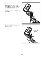
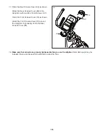
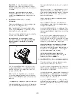
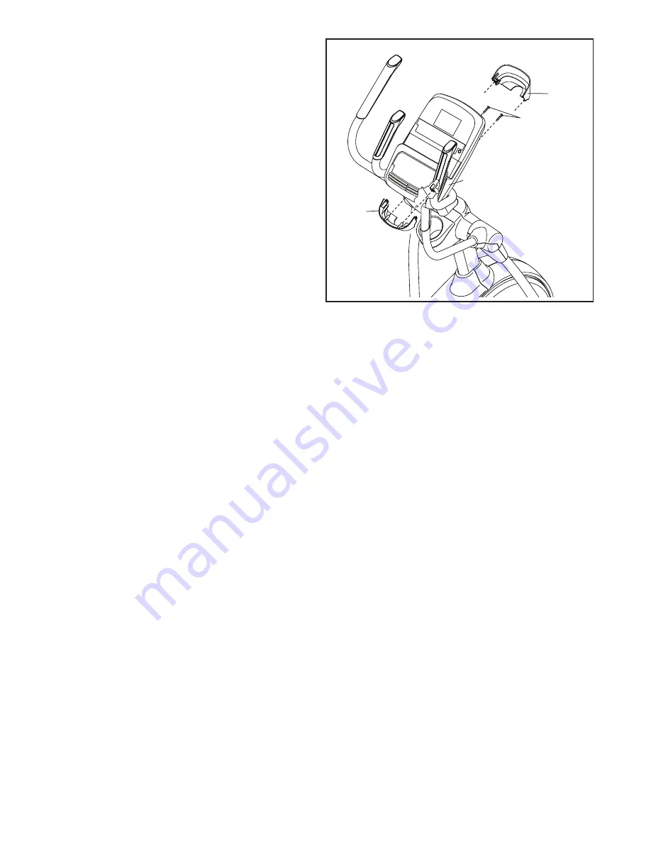
17. Orient the Rear Console Cover (80) as shown.


Attach the Rear Console Cover (80) to the 
Upright (4) with two M4 x 16mm Screws (101).


Orient the Front Console Cover (79) as shown.


Attach the Front Console Cover (79) around 
the Upright (4) by pressing it onto the Rear 
Console Cover (80).

79

4

80

101

18. 

Make sure that all parts are properly tightened before you use the elliptical.

 Note: Extra parts may be 

included. Place a mat beneath the elliptical to protect the floor.

Summary of Contents for 810 E Elliptical

Page 1: ...te the serial number in the space above for reference www proform com Serial Number Decal To register your product and activate your warranty today go to www proformservice com registration For servic...

Page 2: ...he location shown Note The decal s may not be shown at actual size PROFORM is a registered trademark of ICON IP Inc WARNING DECAL PLACEMENT 2 IMPORTANT PRECAUTIONS 3 BEFORE YOU BEGIN 6 PART IDENTIFICA...

Page 3: ...r low power devices such as cell phone chargers into an outlet on the same circuit 10 Do not modify the power cord or use an adapter to connect the power cord to an improper receptacle Keep the power...

Page 4: ...4...

Page 5: ...5 all STANDARD SERVICE PLANS...

Page 6: ...ee the front cover of this manual To help us assist you note the product model number and serial number before contacting us The model number and the location of the serial number decal are shown on t...

Page 7: ...nd of this manual The number following the key number is the quantity needed for assembly Note If a part is not in the hardware kit check to see if it has been preassembled Extra parts may be included...

Page 8: ...ts do not use power tools ASSEMBLY 1 2 With the help of a second person place some of the packing materials not shown under the rear of the Frame 1 Have the second person hold the Frame to prevent it...

Page 9: ...place some of the packing materials not shown under the front of the Frame 1 Have the second per son hold the Frame to prevent it from tipping while you complete this step Attach the Front Stabilizer...

Page 10: ...ip To prevent the Upper Wire 110 from falling into the Upright 4 secure the Upper Wire with the wire tie 4 110 Wire Tie Wire Tie Wire Tie 110 5 5 Tip Avoid pinching the wires Avoid damag ing the indic...

Page 11: ...eg 60 onto the right side of the Pivot Axle 35 Repeat these actions for the Left Upper Body Leg 46 Tighten an M8 x 13mm Screw 82 and an M8 Washer 97 into each end of the Pivot Axle 35 at the same time...

Page 12: ...e Upright 4 connect the wires on the Console to the Upper Wire 110 to the Extension Wire 128 and to the Sensor Wires 63 Insert the excess wire into the Upright 4 or into the Console 7 10 Avoid pinchin...

Page 13: ...the Pedal Arm Axles 64 Next slide an M8 Washer 97 and an Axle Spacer 77 onto an M8 x 13mm Screw 82 and tighten the Screw a few turns into the Pedal Arm Axle 64 While a second person holds the front e...

Page 14: ...nd the Upright 4 by pressing it onto the Rear Upright Cover 81 101 128 A 81 4 117 Avoid pinching the wires 14 14 Identify the Right Upper Body Arm Front Cover 65 and orient it as shown Attach the Righ...

Page 15: ...hown Attach the Right Upper Leg Outer Cover 69 around the Right Upper Body Leg 60 by pressing it onto the Right Upper Body Leg Inner Cover 83 Repeat this step on the other side of the elliptical 60 83...

Page 16: ...01 Orient the Front Console Cover 79 as shown Attach the Front Console Cover 79 around the Upright 4 by pressing it onto the Rear Console Cover 80 79 4 80 101 18 Make sure that all parts are properly...

Page 17: ...er must be connected with a metal screw to a permanent ground such as a properly grounded outlet box cover Some 2 pole receptacle outlet box covers are not grounded Before using an adapter contact a q...

Page 18: ...step onto the pedal that is in the lower position Then step onto the other pedal Push the pedals until they begin to move with a continuous motion Note The pedals can turn in either direc tion It is r...

Page 19: ...ywhere in the world with customizable Google Maps Download training workouts designed to help you reach your personal goals Measure your progress by competing against other users in the iFit community...

Page 20: ...exercise feedback You can also measure your heart rate using the handgrip heart rate monitor or an optional chest heart rate monitor You can also listen to your favorite workout music or audio books...

Page 21: ...ance in either miles or kilometers To find which unit of measurement is selected see step 3 on page 27 HOW TO USE THE MANUAL MODE 1 Begin pedaling or press any button on the console to turn on the con...

Page 22: ...utions per minute rpm Time When the manual mode is selected this display mode will show the elapsed time The matrix offers several display tabs Press the Display button repeatedly until the desired ta...

Page 23: ...d one or two dashes will appear and then your heart rate will be shown For the most accurate heart rate reading hold the contacts for at least 15 seconds If the display does not show your heart rate m...

Page 24: ...segment indicates the target speed or the incline level for the current segment As you exercise you will be prompted to keep your pedaling speed near the target rpm for the cur rent segment When an up...

Page 25: ...d only to provide motivation Your actual pedaling speed may be slower than the target rpm Make sure to pedal at a speed that is comfortable for you Note The calorie goal is an estimate of the number o...

Page 26: ...ill show the name duration maximum ramp incline level and distance of the workout The display will also show the approximate number of calories you will burn during the workout and a profile of the re...

Page 27: ...er Setup To set up a different iFit account but maintain the existing wireless connection follow the instructions in the matrix Note This option will be used rarely Firmware Update For the best result...

Page 28: ...e letter number or symbol When you have finished entering the password press the Done button Next a numerical code and a web address will appear in the matrix Open a web browser on your computer smart...

Page 29: ...er on your computer smart phone tablet or other Wi Fi device Next type in the IP address on the con sole into the URL bar in your browser Example http 192 168 0 1 8080 Your browser will load a web pag...

Page 30: ...equipment does cause harmful interference to radio or television reception which can be determined by turning the equipment off and on try to correct the interference by one or more of the following m...

Page 31: ...p The ramp will move upward and downward as it calibrates When the ramp stops moving the ramp is calibrated Then press the fan decrease button repeatedly to exit the calibration mode HOW TO GREASE THE...

Page 32: ...ht Pedal Arm 58 from the Right Upper Body Leg 60 See EXPLODED DRAWING C on page 39 and EXPLODED DRAWING A on page 37 Remove the Right Roller Arm 59 from the right Crank Arm 20 Then carefully remove th...

Page 33: ...c Exercise If your goal is to strengthen your cardiovascular system you must perform aerobic exercise which is activity that requires large amounts of oxygen for prolonged periods of time For aerobic...

Page 34: ...lles Stretch With one leg in front of the other reach forward and place your hands against a wall Keep your back leg straight and your back foot flat on the floor Bend your front leg lean forward and...

Page 35: ...sher 55 2 Small Axle Cover 56 4 Roller Arm Bushing 57 8 Arm Bearing 58 1 Right Pedal Arm 59 1 Right Roller Arm 60 1 Right Upper Body Leg 61 1 Right Upper Body Arm 62 2 Grip 63 2 Sensor Assembly Wire 6...

Page 36: ...6 2 Disc Ring 117 1 Front Upright Cover 118 1 Shield Cover Cap 119 1 Power Cord 120 1 Ramp Axle 121 6 Small Frame Bushing 122 1 Clevis Pin 123 1 Plastic Spacer 124 2 M4 x 19mm Self tapping Screw 125 2...

Page 37: ...35 37 81 54 54 63 63 71 71 74 79 73 75 80 101 105 105 96 9 102 96 101 101 101 5 5 5 107 101 101 101 5 5 5 5 5 101 101 101 101 101 102 118 116 116 117 110 128 119 111 126 7 EXPLODED DRAWING A Model No...

Page 38: ...3 53 53 55 55 57 57 57 57 57 57 57 57 60 101 61 66 68 101 62 62 64 64 65 67 70 72 69 83 87 76 77 77 77 101 101 77 95 95 95 95 95 95 82 82 82 82 82 82 82 82 96 96 98 98 94 94 97 97 97 97 97 97 97 97 97...

Page 39: ...50 38 24 39 40 40 101 101 50 43 43 48 23 84 42 50 31 27 82 101 78 78 86 86 88 85 85 89 90 90 50 90 91 102 108 108 113 120 121 121 121 121 121 122 102 115 32 114 101 17 123 112 2 28 30 30 33 33 41 105...

Page 40: ...for a minimal trip charge This warranty does not extend to freight damage to the product This warranty will automatically be voided if the product is used as a store display model if the product is p...

Reviews: