
21
HOW TO SET UP THE CONSOLE
Before using the elliptical for the first time, set up the
console.
1. Create an iFit account.
To create an iFit account, or for more informa-
tion about the account, go to www.iFit.com and
click Join iFit.
The iFit.com account creation page will open.
Then, fill in the information fields to create your iFit
account.
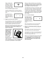
2. Connect to your wireless network.
Note: In order to download iFit workouts and use
some other features of the console, you must be
connected to a wireless network. See HOW TO
CHANGE CONSOLE SETTINGS on page 27 to
connect the console to your wireless network.
3. Check for firmware updates.
See HOW TO CHANGE CONSOLE SETTINGS on
page 27 and check for firmware updates.
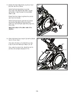
4. Calibrate the incline of the ramp.
See HOW TO CALIBRATE THE RAMP on page
31 and calibrate the incline of the ramp.
The console is now ready for you to begin working out.
The following pages explain the various workouts and
other features that the console offers.
To use the manual mode,
see this page.
To use
an onboard workout,
see page 24.
To use a
set-a-goal workout,
see page 25.
To use an iFit
workout,
see page 26.
To change console
settings
see page 27.
To use the sound system,
see page 29.
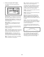
Note: If there is a sheet of plastic on the display,
remove the plastic.
Note: The console can display distance in either miles
or kilometers. To find which unit of measurement is
selected, see step 3 on page 27.
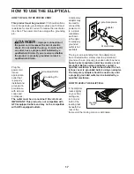
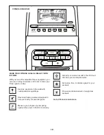
HOW TO USE THE MANUAL MODE
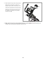
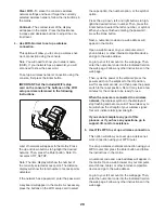
1. Begin pedaling or press any button on the
console to turn on the console.
See HOW TO TURN ON THE POWER on
page 20.
2. Select the manual mode.
The manual mode will be selected automatically
each time you turn on the console.
Note: If the console is connected to iFit through
your wireless network, the display will cycle
between the manual mode and the iFit welcome
message. Press the Manual Control button or
press the Home button repeatedly to select the
manual mode.
You can also press any of the workout buttons
repeatedly to select the manual mode.
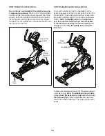
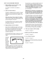
3. Change the resistance of the pedals and the
incline of the ramp as desired.
As you pedal, you can change the resistance of the
pedals. To change the resistance, press one of the
numbered Resistance buttons on the console or
press the Resistance increase and decrease but-
tons on the console or on the right handlebar.
Note: After you press a button, it will take a
moment for the pedals to reach the selected resis-
tance level.
To vary the motion of the pedals, you can change
the incline of the ramp. To change the incline,
press one of the numbered Quick Ramp buttons
on the console, press the Quick Ramp increase
and decrease buttons on the console, or press the
Ramp increase and decrease buttons on the left
handlebar.
Note: After you press a button, it will take a
moment for the ramp to reach the selected
incline level.
Summary of Contents for 810 E Elliptical
Page 4: ...4...


