background image

15

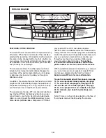
HOW TO USE THE MANUAL MODE

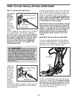
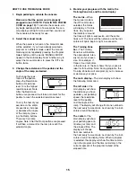
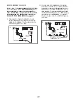
1. Begin pedaling to activate the console.

Make sure that the power cord is properly
plugged in (see HOW TO PLUG IN THE POWER
CORD on page 13). 

To activate the console, sim-

ply begin pedaling. After a few seconds, the con-
sole displays will light. A tone will then sound and
the console will be ready for use. 

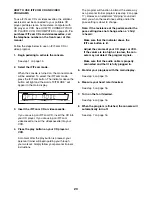
2. Select the manual mode.

When the power is turned on, the manual mode
will be selected. If you have already selected a
program or a different mode, select the manual
mode again by repeatedly pressing the Program
Select button until the words “MANUAL MODE”
appear in the main display. Note: Another way to
select the manual mode is to press the iFIT.com
button twice.

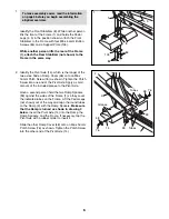
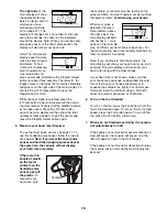
3. Change the resistance of the pedals and the

angle of the ramp as desired.

To change the resis-
tance of the pedals,
press the Resistance
buttons. Resistance
level 10 is the highest
resistance level. Note:
After the Resistance
buttons are pressed, it will take a moment for the
pedals to reach the selected resistance level.

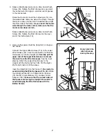
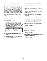
To vary the feel of your
exercise on the ellipti-
cal exerciser, increase
or decrease the angle
of the ramp by press-
ing the Ramp buttons.
There are five ramp
angles. Note: After the Ramp buttons are pressed,
it will take a moment for the ramp to reach the
selected angle. 

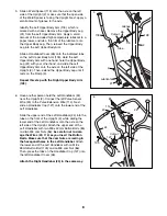
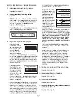
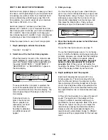
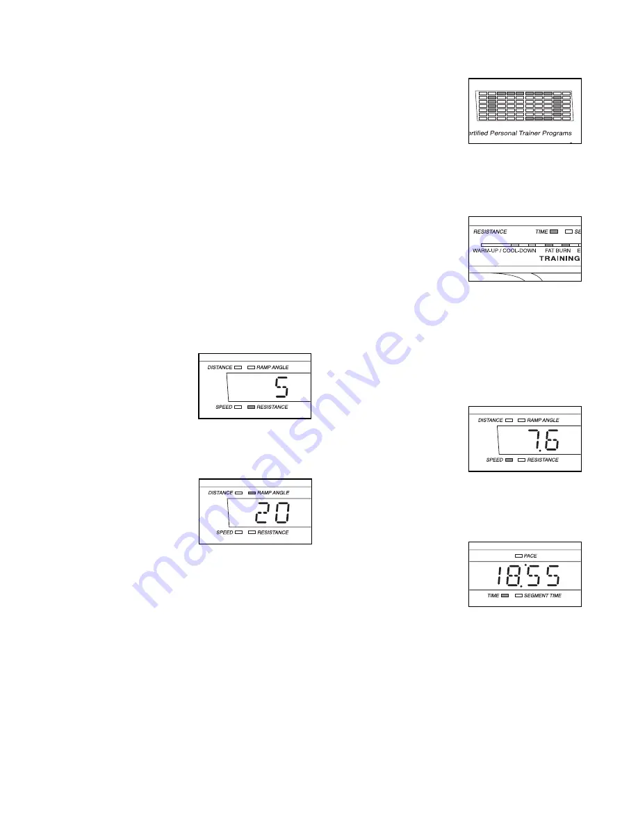
4. Monitor your progress with the matrix, the

Training Zone bar, and the main display.

The matrix

—When

the manual mode or
the iFIT.com mode is
selected, the matrix
will display a 1/4-mile
track. As you pedal,
the indicators around
the track will light in succession until the entire
track is lit. The track will then darken and the indi-
cators will again begin to light in succession.
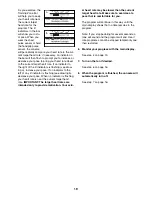
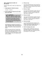
The Training Zone
bar

—The Training

Zone bar will indicate
the approximate inten-
sity level of your exer-
cise. For example, if
three or four indicators
in the bar are lit, the bar shows that your pace is
ideal for fat burning. Note: During programs, the
Training Zone bar will also prompt you to increase
or decrease your pace.
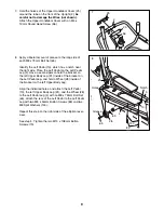
The main display

—The main display will show

the following information:

The left side

of the

main display will show
the distance you have
pedaled, your pedaling
speed, the resistance
level of the pedals,
and the angle of the
ramp. The display will change from one number to
the next every few seconds, as shown by the indi-
cators around the display.

The center

of the

main display will show
your pedaling pace (in

minutes per mile

) and

the elapsed time. The
display will change
from one number to
the next every few seconds, as shown by the indi-
cators around the display. Note: When a program
is selected, the display will show the time remain-
ing in the program and the time remaining in the
current segment of the program instead of the
elapsed time.

Summary of Contents for Club Design 800

Page 1: ...orm com new products prizes fitness tips and much more QUESTIONS As a manufacturer we are commit ted to providing complete customer satisfaction If you have questions or if parts are damaged or missin...

Page 2: ...XPLODED DRAWING 30 ORDERING REPLACEMENT PARTS Back Cover LIMITED WARRANTY Back Cover 2 PROFORM is a registered trademark of ICON IP Inc WARNING DECAL PLACEMENT The warning decal shown here has been ap...

Page 3: ...when exercising do not wear loose clothes that could become caught on your elliptical exer ciser Always wear athletic shoes for foot protection 9 Hold the handgrip pulse sensor or the han dlebars when...

Page 4: ...tions after reading this manual please see the front cover of this manual To help us assist you note the product model number and serial number before con tacting us The model number and the location...

Page 5: ...quired for assembly The number in parentheses below each drawing is the key number of the part from the PART LIST near the end of this manual The number fol lowing the key number is the quantity neede...

Page 6: ...ng 3 below Insert the Pivot Axle 14 into the Ramp the Ramp Spacers and the Frame If necessary tap the Pivot Axle with a rubber mallet to insert it Slide the other Ramp Cover 48 onto an M6 x 16mm Patch...

Page 7: ...pright 2 in the posi tion shown Connect the Upper Wire Harness 115 to the Lower Wire Harness 42 Insert the connectors on the Wire Harnesses up into the Upright 2 Carefully pull the upper end of the Up...

Page 8: ...n extend the Upper Body Leg until it rests on the Ramp 3 Repeat this step with the Right Upper Body Arm 128 26 85 105 86 127 Cutout 86 24 23 2 26 114 20 6 6 Have another person hold the Left Handlebar...

Page 9: ...ave a second person hold the bracket on the left Upper Body Leg 31 inside of the bracket on the Left Pedal Leg and hold a Wheel 28 inside of the bracket on the left Upper Body Leg Align the indicated...

Page 10: ...per Wire Harness 115 to the wire harness on the Console 17 Connect the Pulse Extension Wire 114 to the pulse wire on the Console Next locate the two ground wires that are attached with a screw to the...

Page 11: ...ry the steps below Make sure that the chest pulse sensor is worn exactly as described in step 2 at the left If the chest pulse sensor does not function when posi tioned as described move it slightly l...

Page 12: ...the chest pulse sensor after each use The chest pulse sensor is activated when the electrode areas are wetted and the chest pulse sensor is put on the chest pulse sensor shuts off when it is removed...

Page 13: ...an adapter Note When the power cord is plugged in the ellip tical exerciser s incline system may automatically calibrate itself During the calibration process two dashes will appear in the main displ...

Page 14: ...the included audio cable you can connect the elliptical exerciser to your home stereo portable stereo computer or VCR and play special iFIT com CD and video programs iFIT com CDs and videocassettes ar...

Page 15: ...the selected angle 4 Monitor your progress with the matrix the Training Zone bar and the main display The matrix When the manual mode or the iFIT com mode is selected the matrix will display a 1 4 mi...

Page 16: ...rate accurately If there are thin sheets of plastic on the metal contacts on the handgrip pulse sensor peel off the plastic To measure your heart rate hold the contacts your palms must be resting on t...

Page 17: ...the flashing Current Segment column and the resistance of the pedals will automatical ly change if a different resistance setting is pro grammed for the second segment As you exercise the Training Zo...

Page 18: ...art rate pro gram If you have already entered your age press the Enter button and go to step 4 If you have not entered your age press the Up Arrow or Down Arrow button repeatedly to enter your age and...

Page 19: ...ft of any lit indicator is flashing see drawing b decrease your pace When no indicator is flashing your heart rate is near the current target heart rate IMPORTANT The target heart rates are intended o...

Page 20: ...1 8 Y adapter available at electronics stores Plug the Y adapter into the PHONES jack on your CD player Plug your headphones into the other side of the Y adapter HOW TO CONNECT YOUR PORTABLE STEREO N...

Page 21: ...adapter Plug the Y adapter into the LINE OUT jack on your stereo HOW TO CONNECT YOUR COMPUTER Note If your computer has a 1 8 LINE OUT jack see instruction A If your computer has only a PHONES jack se...

Page 22: ...he adapter into the AUDIO OUT jack on your VCR B Plug one end of the audio cable into the jack beneath the console Plug the other end of the cable into the adapter Plug the adapter into an RCA Y adapt...

Page 23: ...videocassette into your VCR 4 Press the play button on your CD player or VCR A moment after the play button is pressed your personal trainer will begin guiding you through your workout Simply follow...

Page 24: ...ain display 3 Go to your computer and start an Internet con nection 4 Start your Web browser if necessary and go to our website at www iFIT com 5 Follow the desired links on our website to select a pr...

Page 25: ...ght If you have already entered your height press the Enter button If you have not entered your height press the or button to enter your height and then press the Enter button 5 Enter your weight If y...

Page 26: ...ress the Program Select button again Note A combination of letters and numbers may appear in the main display 3 Press the 30 Ramp button The ramp will move all of the way up and then all of the way do...

Page 27: ...ur goal is to strengthen your cardiovascular system you must perform aerobic exercise which is activity that requires large amounts of oxygen for prolonged periods of time For aerobic exercise adjust...

Page 28: ...hing 52 1 Resistance Motor 53 1 Reed Switch Bracket 54 1 Clamp 55 1 Reed Switch Wire 56 1 Return Spring 57 1 Guide Rod 58 1 Resistance Cable 59 1 Flywheel Axle 60 2 Flywheel Bearing 61 2 Eye Bolt 62 2...

Page 29: ...m Tek Screw 109 2 7 6mm Spacer 110 4 Wheel Bushing 111 2 M8 x 19mm Patch Screw 112 2 Wheel 113 1 Belt 114 1 Pulse Extension Wire 115 1 Upper Wire Harness 116 1 Power Cord 117 1 Power Socket 118 1 Left...

Page 30: ...5 68 26 23 85 96 25 24 105 26 68 86 22 21 19 18 15 98 98 98 98 108 98 16 114 116 115 106 107 108 98 69 121 31 120 128 123 123 124 124 123 123 118 120 110 31 122 122 108 119 119 110 110 98 86 127 127 E...

Page 31: ...66 111 83 5 29 65 28 65 11 27 95 125 95 70 73 73 76 64 13 3 12 49 50 64 76 76 48 14 47 47 99 99 47 47 48 76 65 28 65 29 29 10 83 4 88 71 60 90 61 62 37 36 60 59 103 88 61 62 30 111 66 51 51 82 34 101...

Page 32: ...ial damages arising out of or in con nection with the use or performance of the product or damages with respect to any economic loss loss of property loss of revenues or profits loss of enjoyment or u...

Reviews: