background image

12

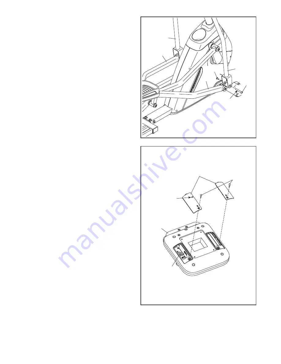
13. Apply grease to an M6 Bolt Set (67).

  Attach the Right Pedal Arm (9) to the Right 

Upper Body Leg (5) with the M6 Bolt Set (67).

  Attach the Left Pedal Arm (10) to the Left 

Upper Body Leg (6) in the same way.

13

6

5

10

67

67

9

Grease

14

14. The Console (30) can use four D batteries (not 

included); alkaline batteries are recommended. 

Do not use old and new batteries together or 

alkaline, standard, and rechargeable batter-

ies together. IMPORTANT: If the Console has 

been exposed to cold temperatures, allow 

it to warm to room temperature before you 

insert batteries. Otherwise, you may dam-

age the console displays or other electronic 

components. Remove the screws (D) and the 

battery covers (E), insert batteries into the bat-

tery compartments, and then reattach the battery 

covers. Make sure to orient the batteries as 

shown by the diagrams inside the battery 

compartments.

  To purchase an optional power adapter, call 

the telephone number on the cover of this 

manual. To avoid damaging the Console (30), 

use only a manufacturer-supplied regulated 

power adapter. Plug one end of the power 

adapter into the receptacle (F) inside the indi-

cated battery compartment, and route the power 

adapter through the notch (G) in the battery 

cover. Then, plug the other end into an outlet 

installed in accordance with all local codes and 

ordinances.

30

D

E

F

G

Summary of Contents for ENDURANCE 320 E

Page 1: ...rence Serial Number Decal USER S MANUAL iconeurope com CUSTOMER SERVICE UNITED KINGDOM Call 0330 123 1045 From Ireland 053 92 36102 Website iconsupport eu E mail csuk iconeurope com Write ICON Health...

Page 2: ...cal is missing or illegible see the front cover of this manual and request a free replacement decal Apply the decal in the loca tion shown Note The decal s may not be shown at actual size PROFORM and...

Page 3: ...surface with at least 3 ft 0 9 m of clearance in the front and rear of the elliptical and 2 ft 0 6 m on each side To protect the floor or carpet from dam age place a mat under the elliptical 8 Inspec...

Page 4: ...se see the front cover of this manual To help us assist you note the product model number and serial number before contacting us The model number and the location of the serial number decal are shown...

Page 5: ...needed for assembly Note If a part is not in the hardware kit check to see if it has been preassembled Extra parts may be included M8 Locknut 60 6 M8 Washer 63 6 M4 x 16mm Screw 56 4 M10 x 100mm Screw...

Page 6: ...nder the front of the Frame 1 Have the second per son hold the Frame to prevent it from tipping while you complete this step Attach the Front Stabilizer 12 to the Frame 1 with two M10 x 100mm Screws 7...

Page 7: ...ng materials from under the Frame 1 4 Orient the Upright 2 and the Accessory Tray 50 as shown Slide the Accessory Tray upward onto the Upright Have a second person hold the Upright 2 near the Frame 1...

Page 8: ...ws yet Finish attaching the Upright 2 with an M10 x 60mm Bolt 72 and an M10 Small Locknut 91 do not fully tighten the Bolt yet Make sure that the Small Locknut is in the hexagonal hole B Do not press...

Page 9: ...knuts 60 make sure that the Locknuts are in the hexagonal holes C Start all the Bolts and then tighten them Attach the Left Upper Body Arm 4 to the Left Upper Body Leg 6 in the same way 61 61 18 63 63...

Page 10: ...ith four M4 x 16mm Self tapping Screws 57 start all the Screws and then tighten them Repeat this step on the other side of the elliptical 9 10 Identify the Front and Rear Upright Covers 51 54 and orie...

Page 11: ...63 Attach the Left Roller Arm 8 in the same way 11 61 Grease 44 63 8 7 13 12 Apply grease to the axle on the Right Roller Arm 7 Then identify the Right Pedal Arm 9 orient it as shown and slide it ont...

Page 12: ...se you may dam age the console displays or other electronic components Remove the screws D and the battery covers E insert batteries into the bat tery compartments and then reattach the battery covers...

Page 13: ...may become damaged Insert the excess wire into the Upright 2 Tip Avoid pinching the wires Attach the Console 30 to the Upright 2 with four M4 x 16mm Screws 56 start all the Screws and then tighten the...

Page 14: ...IPTICAL If the elliptical rocks slightly on your floor during use turn one or both of the level ing feet beneath the rear of the frame until the rocking motion is eliminated HOW TO USE THE TABLET HOLD...

Page 15: ...rn in either direc tion It is recommended that you turn the pedals in the direction shown by the arrow however for variety you can turn the pedals in the opposite direction To dismount the elliptical...

Page 16: ...e console also offers a selection of preset work outs Each preset workout automatically changes the resistance of the pedals and prompts you to maintain a target speed as it guides you through an effe...

Page 17: ...r disappear in the speed meter Note During a preset workout this display will show a target speed zone for each segment of the workout The upper display This display will show your pedal ing speed in...

Page 18: ...are sheets of plastic on the metal contacts on the handgrip heart rate monitor remove the plastic In addition make sure that your hands are clean To measure your heart rate hold the handgrip heart rat...

Page 19: ...that are within a few RPMs of the target speed for the segment The solid bars represent your actual pedaling speed As you exercise keep your pedaling speed within the target zone for the current segm...

Page 20: ...OLE The console supports BLUETOOTH connections to tablets via the iFit Bluetooth Tablet app and to compat ible heart rate monitors Note Other BLUETOOTH connections are not supported 1 Download and ins...

Page 21: ...he console until the LED on the console turns solid green Note All BLUETOOTH connections between the console and other devices including any tablets heart rate monitors and so forth will be disconnect...

Page 22: ...hen moving on the Track 11 apply a small amount of the included PTFE grease to a paper towel Next spread a thin layer of grease evenly along the Track where the Rollers move Then wipe off any excess g...

Page 23: ...M8 Washer not shown from the Right Roller Arm 7 and the right Crank Arm not shown Gently move the Right Roller Arm out of the way Then use a standard screwdriver and gently pry the Outer and Inner Cra...

Page 24: ...c Exercise If your goal is to strengthen your cardiovascular system you must perform aerobic exercise which is activity that requires large amounts of oxygen for prolonged periods of time For aerobic...

Page 25: ...Inner Crank Cover 54 1 Rear Upright Cover 55 1 Drive Belt 56 15 M4 x 16mm Screw 57 20 M4 x 16mm Self tapping Screw 58 1 M4 x 12mm Bright Screw 59 6 M8 x 38mm Bolt 60 10 M8 Locknut 61 10 M8 x 20mm Scre...

Page 26: ...90 25 22 24 27 29 31 34 34 83 51 54 83 38 38 39 33 35 40 43 61 61 48 56 56 56 50 45 49 58 56 56 57 57 57 56 57 57 56 56 57 56 56 55 84 68 80 80 64 64 64 64 72 74 74 74 74 74 76 78 75 91 71 65 65 69 30...

Page 27: ...AWING B 4 6 8 10 5 3 7 9 16 18 44 17 17 60 60 36 36 19 19 41 57 85 46 42 82 47 57 57 59 59 61 63 61 67 67 70 70 79 86 86 57 85 87 87 83 37 37 83 44 61 63 63 21 88 84 84 88 13 52 53 66 Model No PFEVEL3...

Page 28: ...T and the EXPLODED DRAWING near the end of this manual ORDERING REPLACEMENT PARTS This electronic product must not be disposed of in municipal waste To preserve the environment this product must be re...

Reviews: