background image

5

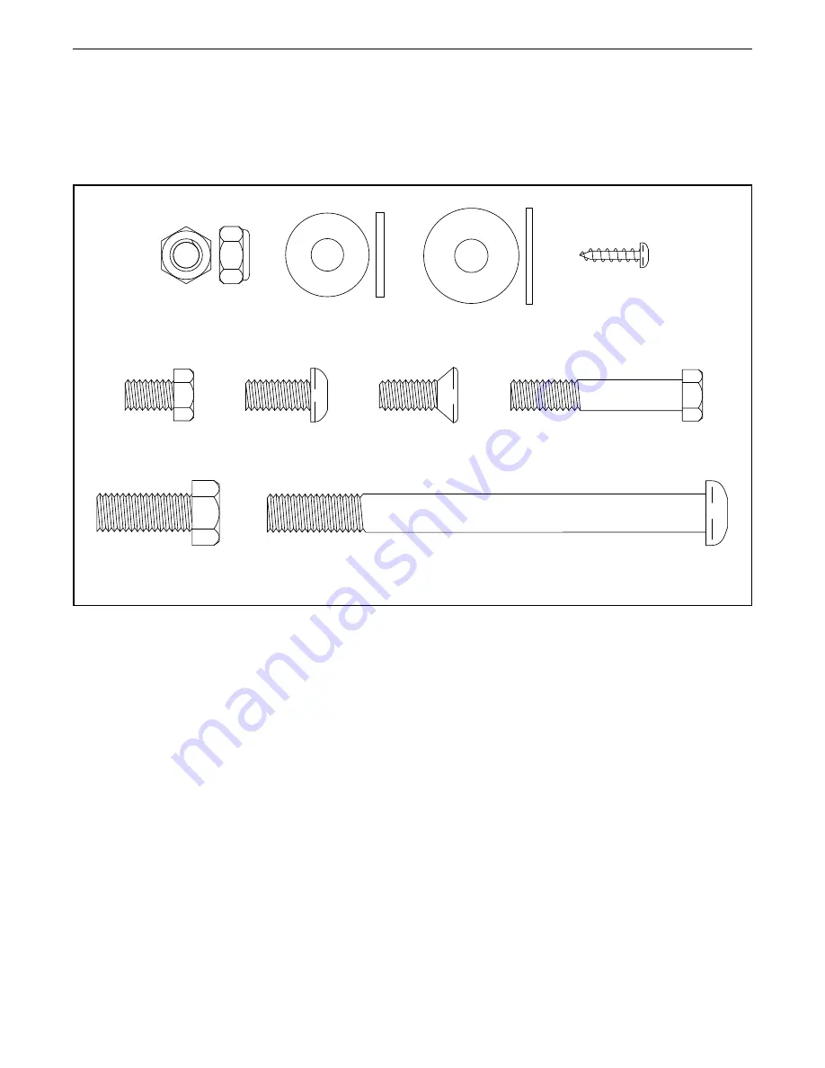
PART IDENTIFICATION CHART

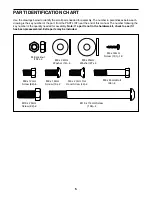
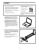
Use the drawings below to identify the small parts needed for assembly. The number in parentheses below each 

drawing is the key number of the part, from the PART LIST near the end of this manual. The number following the 

key number is the quantity needed for assembly. Note: If a part is not in the hardware kit, check to see if it 

has been preassembled. Extra parts may be included.

M10 x 114mm Screw 

(104)–4

M8 Locknut 

(102)–4

M4 x 16mm 

Screw (101)–18

M8 x 12mm 

Screw (82)–6

M8 x 45mm Bolt 

(96)–4

M8 x 20mm Flat 

Head Screw (48)–2

M8 x 22mm 

Washer (14)–4

M10 x 25mm 

Screw (92)–2

M8 x 16mm

Screw (13)–2

M8 x 25mm 

Washer (97)–2

Summary of Contents for ENDURANCE 420 E

Page 1: ...number in the space above for reference CUSTOMER SERVICE UNITED KINGDOM Call 0330 123 1045 From Ireland 053 92 36102 Website iconsupport eu E mail csuk iconeurope com Write ICON Health Fitness Ltd Un...

Page 2: ...LIPTICAL 15 HOW TO USE THE CONSOLE 17 MAINTENANCE AND TROUBLESHOOTING 23 EXERCISE GUIDELINES 25 PART LIST 27 EXPLODED DRAWING 29 ORDERING REPLACEMENT PARTS Back Cover RECYCLING INFORMATION Back Cover...

Page 3: ...or covered patio or near water 7 Place the elliptical on a level surface with at least 3 ft 0 9 m of clearance in the front and rear of the elliptical and 2 ft 0 6 m on each side To protect the floor...

Page 4: ...ing this manual please see the front cover of this manual To help us assist you note the product model number and serial number before contacting us The model number and the location of the serial num...

Page 5: ...manual The number following the key number is the quantity needed for assembly Note If a part is not in the hardware kit check to see if it has been preassembled Extra parts may be included M10 x 114...

Page 6: ...identify small parts see page 5 In addition to the included tool s assembly requires the following tools one Phillips screwdriver two adjustable wrenches one rubber mallet Assembly may be easier if y...

Page 7: ...with two M10 x 114mm Screws 104 Then remove the packing materials from under the front of the Frame 1 1 104 77 59 45 13 4 Using a plastic bag to keep your fingers clean apply some of the included grea...

Page 8: ...Wire 110 from fall ing into the Upright 4 secure the Main Wire with the wire tie A 4 110 A 6 5 Tip Avoid pinching the Main Wire 110 Have a second person hold the Upright 4 on the Frame 1 Tip Two M10 x...

Page 9: ...5mm Washer 97 Repeat this step for the Left Upper Body Leg 46 46 4 Grease 8 60 54 82 97 8 Orient the Right Pedal Arm 58 as shown and then apply grease to the axle Insert the Right Pedal Arm 58 into th...

Page 10: ...he Console 7 Tip Avoid pinching the Main Wire 110 Attach the Console 7 to the Upright 4 with four M4 x 16mm Screws 101 start all the Screws and then tighten them 101 82 14 60 64 Grease 58 4 110 101 9...

Page 11: ...ch it to the Upright 4 with two M4 x 16mm Screws 101 4 101 37 12 101 81 37 12 Orient a Lower Tray Cover 81 as shown and attach it to the right side of the Accessory Tray 37 with two M4 x 16mm Screws 1...

Page 12: ...sure that the Locknuts are in the hexagonal holes C Repeat this step for the Left Upper Body Arm 47 60 61 47 96 102 C 75 4 94 101 73 74 14 Orient the Front Shield Cover 94 and the Center Shield Cover...

Page 13: ...ght Leg Inner Cover 83 Attach the Right Leg Outer and Inner Covers 69 83 to each other with an M4 x 16mm Screw 101 Repeat this step on the other side of the elliptical 60 101 69 15 16 65 60 101 66 16...

Page 14: ...ical Note To plug the Power Adapter 79 into an outlet see HOW TO PLUG IN THE POWER ADAPTER on page 15 18 Make sure that all parts are properly tightened before you use the elliptical Place a mat benea...

Page 15: ...l local codes and ordinances HOW TO LEVEL THE ELLIPTICAL If the elliptical rocks slightly on your floor during use turn one or both of the leveling feet B beneath the rear of the frame or turn the lev...

Page 16: ...e pedals can turn in either direction It is recommended that you turn the ped als in the direction shown by the arrow however for variety you can turn the pedals in the opposite direction To dismount...

Page 17: ...d the iFit app to your smart device and connect it to the console With the iFit app you can access a large and varied library of iFit video workouts create your own work outs track your workout result...

Page 18: ...ve pedaled in miles or kilometers To change the unit of measurement press the Std Metric button Pace Your pedaling speed in minutes per mile or minutes per kilometer To change the unit of measurement...

Page 19: ...ll Bluetooth Smart heart rate monitors A compatible chest heart rate monitor is included with some models If a chest heart rate monitor is included see THE CHEST HEART RATE MONITOR in this manual to l...

Page 20: ...rate monitor before you connect your smart device See HOW TO CONNECT YOUR HEART RATE MONITOR TO THE CONSOLE on page 21 3 Connect your smart device to the console Press the iFit Sync button on the con...

Page 21: ...do not move for several seconds the console will pause If the pedals do not move for several minutes and the buttons are not pressed the console will turn off and the display will be reset HOW TO CONN...

Page 22: ...icians to identify whether the display is working correctly Button Test This screen is intended to be used by service technicians to identify whether a certain button is working correctly Total Time T...

Page 23: ...le use only a manufacturer supplied regulated power adapter HOW TO ADJUST THE REED SWITCH If the console does not display correct feedback the reed switch should be adjusted To adjust the reed switch...

Page 24: ...the power adapter Next locate the Access Cover 3 on the Right Shield 74 Remove the M4 x 16mm Screw 101 and then remove the Access Cover Next locate and loosen the Idler Screw 89 Tighten the Drive Belt...

Page 25: ...ystem you must perform aerobic exercise which is activity that requires large amounts of oxygen for prolonged periods of time For aerobic exercise adjust the intensity of your exercise until your hear...

Page 26: ...lles Stretch With one leg in front of the other reach forward and place your hands against a wall Keep your back leg straight and your back foot flat on the floor Bend your front leg lean forward and...

Page 27: ...rew 51 2 Roller 52 2 Pedal Arm Cap 53 2 Axle Cover 54 2 Pivot Spacer 55 2 Retainer 56 4 Roller Arm Bushing 57 6 Large Arm Bearing 58 1 Right Pedal Arm 59 1 Right Roller Arm 60 1 Right Upper Body Leg 6...

Page 28: ...crew 109 2 M10 x 60mm Bolt 110 1 Main Wire 111 1 Power Wire Receptacle 112 2 M4 x 16mm Self tapping Screw Assembly Tool Grease Packet User s Manual Key No Qty Description Key No Qty Description Note S...

Page 29: ...63 71 73 75 101 101 101 101 101 92 31 5 101 101 101 101 94 105 80 101 101 101 5 101 46 52 45 44 47 49 51 56 55 35 57 68 62 64 67 70 72 32 76 77 95 13 48 82 97 100 100 8 17 82 14 14 82 96 102 98 95 11...

Page 30: ...0 79 111 6 10 2 18 15 106 20 101 101 101 28 30 22 33 40 41 43 43 42 88 93 89 90 91 108 21 84 102 101 102 30 101 36 20 34 104 26 109 112 23 40 82 82 99 25 78 86 78 86 92 90 108 38 50 104 1 24 19 101 12...

Page 31: ...1 11 5 5 105 5 101 101 32 95 17 52 29 58 57 57 103 103 87 59 57 35 77 13 56 55 48 56 51 53 95 98 95 8 71 60 101 61 66 62 64 65 69 83 101 27 101 101 101 3 82 82 96 14 14 101 102 82 97 100 100 54 11 11...

Page 32: ...T and the EXPLODED DRAWING near the end of this manual ORDERING REPLACEMENT PARTS This electronic product must not be disposed of in municipal waste To preserve the environment this product must be re...

Reviews: