background image

14

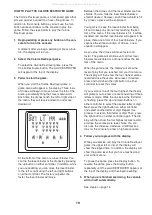
HOW TO USE THE MANUAL MODE

Note: If there is a sheet of clear plastic on the face

of the console, remove the plastic.

1. Begin pedaling or press any button on the con-

sole to turn on the console.

A moment after you begin pedaling or press a but-

ton, the display will turn on.

2. Select the manual mode.

Each time you turn

on the console,

the manual mode

will be selected. If

you have selected

a workout, reselect

the manual mode

by pressing either of the Workouts buttons repeat-

edly until the word MANUAL appears in the lower

left corner of the display.

3. Change the resistance of the pedals as

desired.

As you pedal,

change the resis-

tance of the ped-

als by pressing

any of the

Resistance

increase and

decrease buttons. Note: After you press the but-

tons, it will take a moment for the pedals to reach

the selected resistance level.

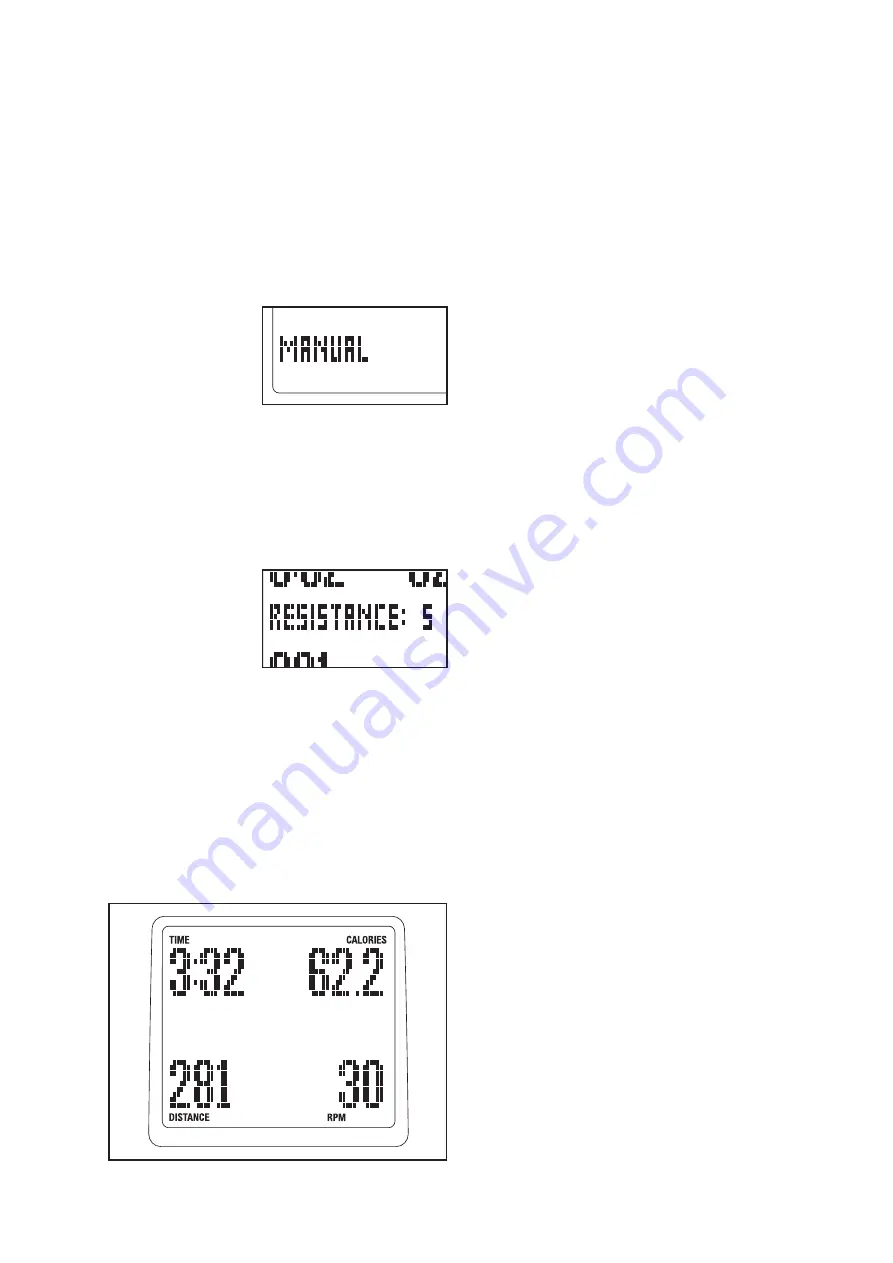
4. Follow your progress with the display.

The upper left corner of the display

will show

the elapsed time. Note: When a workout is select-

ed, the display will show the time remaining in the

workout instead of the elapsed time.

The lower left corner of the display

will show

the distance, in total revolutions, you have

pedaled.

The upper right corner of the display

will show

the approximate number of calories you have

burned. The upper right corner of the display will

also show your heart rate when you use the hand-

grip heart rate monitor (see step 5 on page 15).

The lower right corner of the display

will show

your pedaling pace in revolutions per minute

(rpm).

The center of the display

will show the resis-

tance level of the pedals for a few seconds each

time the resistance level changes.

You can also view selected information at a larger

size. Press the Display Mode button repeatedly to

view time and distance information, time and calo-

rie information, or time and pace information.

Press the Display Mode button again to view all

information.

To adjust the volume level of the console, press

the increase and decrease buttons located next to

the Enter button. There are five volume levels.

The console has three backlight options. The “On”

option keeps the backlight on while the console is

on. To conserve the batteries, the “Auto” option

keeps the backlight on only while you are pedal-

ing. The “Off” option turns the backlight off. To

select a backlight option, first press and hold down

the Display Mode button for several seconds.

Next, press the Resistance increase button to

select the desired backlight option. Then, press

the Display Mode button to save your selection.

All manuals and user guides at all-guides.com

Summary of Contents for PFEL06611.0

Page 1: ...NUAL QUESTIONS If you have questions or if parts are damaged or missing DO NOT CONTACT THE STORE please contact Customer Care IMPORTANT Please register this product see the limited warranty on the back cover of this manual before contacting Customer Care CALL TOLL FREE 1 888 533 1333 Mon Fri 6 a m 6 p m MT Sat 8 a m 4 p m MT ON THE WEB www proformservice com www proform com All manuals and user gu...

Page 2: ...uest a free replacement decal Apply the decal in the location shown Note The decal s may not be shown at actual size WARNING DECAL PLACEMENT 2 IMPORTANT PRECAUTIONS 3 BEFORE YOU BEGIN 4 ASSEMBLY 5 HOW TO USE THE ELLIPTICAL 12 MAINTENANCE AND TROUBLESHOOTING 21 EXERCISE GUIDELINES 22 PART LIST 25 EXPLODED DRAWING 26 ORDERING REPLACEMENT PARTS Back Cover LIMITED WARRANTY Back Cover All manuals and u...

Page 3: ...on each side To protect the floor or carpet from damage place a mat under the elliptical 7 Inspect and properly tighten all parts regularly Replace any worn parts immediately 8 Keep children under age 12 and pets away from the elliptical at all times 9 The elliptical should not be used by persons weighing more than 275 lbs 125 kg 10 Wear appropriate clothes while exercising do not wear loose cloth...

Page 4: ...ee the front cover of this manual To help us assist you note the product model number and serial number before contacting us The model number and the location of the serial number decal are shown on the front cover of this manual Before reading further please familiarize yourself with the parts that are labeled in the drawing below Heart Rate Monitor Game Controller Power Jack Handlebar Wheel Peda...

Page 5: ...ing materials Do not dispose of the packing materials until assembly is completed Assembly requires the included tool s and your own Phillips screwdriver adjustable wrench and rubber mallet Use the drawings below to identify small parts The number in parentheses below each drawing is the key num ber of the part from the PART LIST near the end of this manual The number following the parentheses is ...

Page 6: ...econd person tips the Frame 1 backward attach the Stabilizer to the Frame with the two M10 x 120mm Screws 58 2 Identify the Right Handlebar 36 which is marked with an R sticker and orient it as shown Attach the Right Handlebar to the Frame 1 with the Upper Body Cap 34 and three M6 x 18mm Screws 57 Repeat this step to attach the Left Handlebar 22 58 49 2 1 1 8 8 22 57 36 34 To make assembly easier ...

Page 7: ...ight Tie the lower end of the wire tie to the Wire Harness 46 Next pull the upper end of the wire tie upward out of the top of the Upright Then untie and discard the wire tie Tip Do not allow the Wire Harness to fall into the Upright Use a piece of tape or an elastic band to hold the Wire Harness in place until step 4 Tip Avoid pinching the Wire Harness 46 during this step Insert the Upright 3 int...

Page 8: ...e Link Tube inside the left Link Arm and then position the Left Pedal Leg 24 and the left Link Arm as shown Apply a small amount of the included grease to a Barrel Nut 56 Insert the Barrel Nut through the indicated holes in the Left Pedal Leg 24 and the left Link Arm 25 Then insert the Barrel Nut through the Link Tube 30 inside the left Link Arm Tighten an M6 x 14mm Flat Head Screw 55 into the Bar...

Page 9: ...le of the Roller 27 through the right Link Arm 25 make sure that the Roller is on the inner side of the Link Arm Attach the Roller with an M10 x 15mm Screw 71 and an M10 x 22mm x 1 5mm Washer 63 Tip Use a wrench to hold the axle of the Roller firmly in place while you tighten the Screw into the axle Repeat this step to attach the other Roller 27 to the left Link Arm 25 24 77 61 26 26 All manuals a...

Page 10: ...p Cover 7 to the Ramp 2 with six 8 x 1 2 Screws 79 9 79 79 79 79 7 10 While a second person tips the Frame 1 for ward tighten a Foot 9 into the underside of the Frame 10 2 9 1 All manuals and user guides at all guides com ...

Page 11: ...t the floor or carpet from damage place a mat under the elliptical Plug the power supply into the socket at the front of the elliptical see HOW TO PLUG IN THE POWER SUPPLY on page 12 IMPORTANT If the elliptical has been exposed to cold temperatures allow it to warm to room temperature before plugging in the power cord If you do not do this the console dis plays or other electronic components may b...

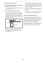
Page 12: ...inst one of the front wheels Pull on the upright and have a second person lift the rear of the track until the ellip tical will roll on the front wheels Carefully move the elliptical to the desired location and then lower it to the floor HOW TO EXERCISE ON THE ELLIPTICAL To mount the elliptical hold the handlebars and step onto the pedal that is in the lower position Then step onto the other pedal...

Page 13: ...on each side To protect the floor or carpet from damage place a mat under the elliptical 7 Inspect and properly tighten all parts regularly Replace any worn parts immediately 8 Keep children under age 12 and pets away from the elliptical at all times 9 The elliptical should not be used by persons weighing more than 275 lbs 125 kg 10 Wear appropriate clothes while exercising do not wear loose cloth...

Page 14: ...ner of the display will show the approximate number of calories you have burned The upper right corner of the display will also show your heart rate when you use the hand grip heart rate monitor see step 5 on page 15 The lower right corner of the display will show your pedaling pace in revolutions per minute rpm The center of the display will show the resis tance level of the pedals for a few seco...

Page 15: ...e handgrip heart rate monitor the display will show your heart rate for up to 30 seconds If the display does not show your heart rate make sure that your hands are positioned as described Be careful not to move your hands excessively or to squeeze the contacts too tightly For optimal performance clean the contacts using a soft cloth never use alcohol abrasives or chemicals to clean the contacts 6 ...

Page 16: ...level and or target rpm is programmed for the next segment the resistance level and or the target rpm will flash in the display for a few seconds to alert you The resistance of the pedals will then change As you exercise you will be prompt ed to keep your pedaling pace near the target rpm set ting for the current segment When an upward pointing arrow appears in the display increase your pace When ...

Page 17: ...nce level and or target rpm is programmed for the next segment the resistance level and or target rpm will flash in the display for a few seconds to alert you The resistance of the pedals will then change As you exercise you will be prompt ed to keep your pedaling pace near the target rpm set ting for the current segment When an upward pointing arrow appears in the display increase your pace When ...

Page 18: ...e speed of the blocks the faster you pedal the more slowly the blocks will fall giving you extra time to position and orient the blocks The game will con tinue until any part of a stacked block reaches the top of the arena When the game ends the display will show your final score and the level of play that you reached The display will then show the four highest scores recorded since the scores wer...

Page 19: ...l be disabled and another laser blaster will appear in its place there are a total of four laser blasters If you vaporize the entire squadron of drones a new squadron will appear As you play the drones will move faster and faster The game will continue until all four laser blasters are disabled or a drone reaches the bot tom of the arena When the game ends the display will show the level of play t...

Page 20: ...ter you select a workout the voice of a personal trainer will begin guiding you through your workout iFit workouts function in the same way as classic workouts To use the workout see steps 3 to 6 on page 17 3 When you are finished exercising remove the iFit card Remove the iFit card when you are finished exer cising Store the iFit card in a secure place HOW TO USE THE SOUND SYSTEM To play music or...

Page 21: ...o not do this the console dis plays or other electronic components may become damaged To replace the batteries remove the two screws which are marked with a battery symbol from the back of the console and remove the battery cover Insert four 1 5V D batteries into the console Orient the batteries as shown by the markings inside the bat tery compartment Then reattach the battery cover HEART RATE MON...

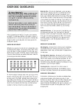
Page 22: ...your cardiovascular system you must perform aerobic exercise which is activity that requires large amounts of oxygen for prolonged periods of time For aerobic exercise adjust the intensity of your exercise until your heart rate is near the highest number in your training zone WORKOUT GUIDELINES Warming Up Start with 5 to 10 minutes of stretching and light exercise A warm up increases your body tem...

Page 23: ...eg in front of the other reach forward and place your hands against a wall Keep your back leg straight and your back foot flat on the floor Bend your front leg lean forward and move your hips toward the wall Hold for 15 counts then relax Repeat 3 times for each leg To cause further stretching of the achilles ten dons bend your back leg as well Stretches Calves achilles ten dons and ankles 4 Quadri...

Page 24: ...24 NOTES All manuals and user guides at all guides com ...

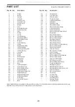
Page 25: ...crew 52 2 M8 x 50mm Hex Screw 53 2 Large Snap Ring 54 2 Small Snap Ring 55 2 M6 x 14mm Flat Head Screw 56 2 Barrel Nut 57 6 M6 x 18mm Screw 58 2 M10 x 120mm Screw 59 2 M10 x 20mm Screw 60 4 M6 Nylon Locknut 61 4 M8 x 55mm Screw 62 2 M8 x 50mm Screw 63 2 M10 x 22mm x 1 5mm Washer 64 4 M10 x 27mm Screw 65 4 M8 x 19mm Screw 66 19 8 x 3 4 Screw 67 3 M4 x 16mm T Screw 68 4 8 x 2 Screw 69 8 M6 x 12mm Sc...

Page 26: ...AWING A Model No PFEL06611 0 R0911A 4 5 6 7 17 33 35 35 40 66 67 66 66 66 66 66 79 79 66 66 66 79 67 66 81 81 81 81 66 82 82 67 81 81 79 79 79 79 All manuals and user guides at all guides com a l l g u i d e s c o m ...

Page 27: ...8 29 29 48 39 30 30 31 31 32 32 34 34 37 38 25 41 42 43 36 44 44 9 9 45 45 46 47 14 49 50 50 51 78 52 52 53 53 54 54 55 55 56 56 57 57 58 59 59 74 73 73 74 71 71 60 77 77 61 61 76 76 62 62 70 70 63 63 64 65 65 69 68 69 72 80 79 79 51 78 83 EXPLODED DRAWING B Model No PFEL06611 0 R0911A All manuals and user guides at all guides com ...

Page 28: ...ht damage to the product This warranty will automati cally be voided if the product is used as a store display model if the product is purchased or transported outside the USA if all instructions in this manual are not followed if the product is abused or improperly or abnormally used or if the product is used for commercial or rental purposes No other warranty beyond that specifically set forth a...

Reviews: