background image

8

9. Make sure that all parts of the elliptical exerciser are properly tightened. Note: Some hardware may be

left over after assembly is completed. To protect the floor or carpet from damage, place a mat under the ellip-

tical exerciser.

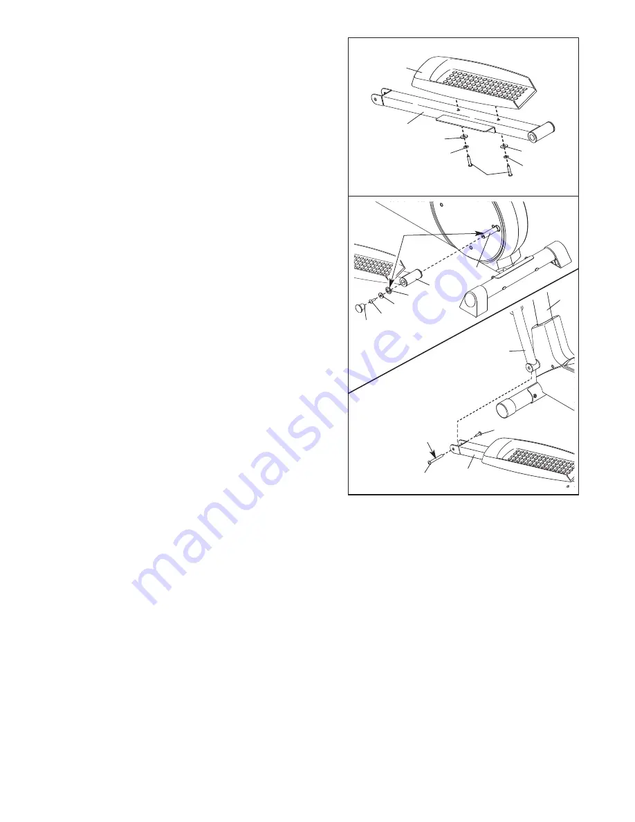
8. Apply a small amount of grease to the axle on the left

Disc Crossbar (16). 

Slide the Left Pedal Leg (11) onto the axle on the left

Disc Crossbar (16). Apply a small amount of grease to

a Large Wave Washer (76) and press it onto the end of

the Left Pedal Leg. Next, slide an M10 Washer (35)

onto an M10 x 27mm Patch Screw (40), and tighten the

Patch Screw into the axle. Then, press a Pedal Leg

Endcap (74) into the Left Pedal Leg.

Hold the lower end of the left Handlebar Leg (5) inside

of the bracket on the front of the Left Pedal Leg (11).

Next, apply grease to an M6 Bolt Set (25). Attach the

Handlebar Leg to the Left Pedal Leg with the Bolt Set.

Do not overtighten the Bolt Set; the Handlebar Leg

must pivot freely.

Attach the Right Pedal Leg (not shown) to the right side

of the elliptical exerciser in the same way.

See step 5. Tighten the M10 x 74mm Button Bolts (7)

in the Upright (2). See step 6. Tighten the M8 x 45mm

Button Bolts (50) in the Handlebar Legs (5).

Grease

Grease

16

25

11

40

74

35

76

11

25

5

2

7

27

71

11

13

71

28

28

7. Identify the Left Pedal Leg (11), which is marked with a

sticker. Attach the Left Pedal (13) to the Left Pedal Leg

with two M8 x 52mm Button Screws (27), two M8 Split

Washers (28), and two M8 Washers (71).

Attach the Right Pedal (not shown) in the same way. 

8

Summary of Contents for PFEL2926.0

Page 1: ...0125 QUESTIONS As a manufacturer we are com mitted to providing complete customer satisfaction If you have questions or if parts are damaged or missing PLEASE CONTACT OUR CUSTOMER SERVICE DEPARTMENT D...

Page 2: ...OW TO USE THE ELLIPTICAL EXERCISER 9 MAINTENANCE AND TROUBLESHOOTING 12 CONDITIONING GUIDELINES 13 PART LIST 14 EXPLODED DRAWING 15 HOW TO ORDER REPLACEMENT PARTS Back Cover LIMITED WARRANTY Back Cove...

Page 3: ...appropriate athletic clothes and athlet ic shoes while using the elliptical exerciser 9 Always hold the handles on the console or the handlebars while mounting dismounting or using the elliptical exe...

Page 4: ...estions after reading this manual see the front cover of this manual To help us assist you please note the prod uct model number and serial number before contact ing us The model number is PFEL2926 0...

Page 5: ...small parts The number in parenthe ses below each drawing is the key number of the part The number following the parentheses is the quantity needed for assembly Note Some small parts shown in the asse...

Page 6: ...the battery cover 23 Batteries Batteries Battery Cover 3 4 While another person holds the Console 23 in the position shown connect the console wire to the Extension Wire 68 Attach the Console 23 to th...

Page 7: ...the post on the Left Handlebar 6 Next slide the Left Handlebar onto the Pivot Axle 26 Slide a Handlebar Washer 55 and a Wave Washer 69 onto an M8 x 25mm Patch Screw 56 and tighten the Patch Screw into...

Page 8: ...al Leg Hold the lower end of the left Handlebar Leg 5 inside of the bracket on the front of the Left Pedal Leg 11 Next apply grease to an M6 Bolt Set 25 Attach the Handlebar Leg to the Left Pedal Leg...

Page 9: ...ve the pedal disks in the direction shown by the arrow however for variety you can turn the pedal disks in the opposite direction To dismount the elliptical exerciser wait until the ped als come to a...

Page 10: ...levels The selected resistance level will be shown in the upper display Note After a button is pressed it will take a moment for the pedals to reach the selected resistance level Follow your progress...

Page 11: ...will be shown For the most accurate heart rate reading continue to hold the handgrips for about 30 seconds Note When you first hold the handgrips the display will show your heart rate continuously fo...

Page 12: ...e the Right Side Shield 4 Remove all Screws 52 from the Left Side Shield 3 and move the Left Side Shield Next see the drawing below and locate the Reed Switch 53 Loosen but do not remove the indicated...

Page 13: ...your cardiovascular sys tem your exercise must be aerobic Aerobic exer cise is activity that requires large amounts of oxygen for prolonged periods of time This increases the demand on the heart to pu...

Page 14: ...5mm Carriage Bolt 35 4 M10 Washer 36 2 M3 x 16mm Screw 37 2 Pedal Arm Bushing 38 5 M8 Nylon Locknut 39 2 Inside Pedal Arm Bushing 40 2 M10 x 27mm Patch Screw 41 2 M6 x 18mm Bolt 42 6 M5 x16mm Screw 43...

Page 15: ...33 51 15 70 34 9 33 33 20 20 16 61 54 52 53 38 65 62 55 56 38 50 48 47 49 24 56 55 57 35 33 58 21 21 34 60 60 60 23 52 52 64 52 41 52 41 64 49 48 47 49 49 46 16 42 25 25 25 25 15 66 66 35 67 7 45 59...

Page 16: ...ranty does not extend to any product or damage to a product caused by or attributable to freight damage abuse misuse improper or abnormal usage or repairs not provided by an ICON authorized service ce...

Reviews: