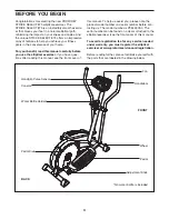
background image

6

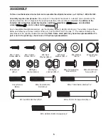
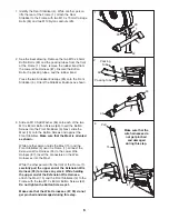
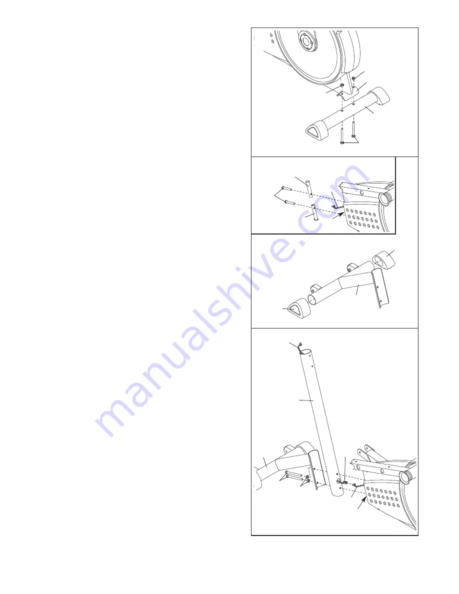
1. Identify the Rear Stabilizer (4). While another person

lifts the rear of the Frame (1), attach the Rear

Stabilizer to the Frame with two M10 x 75mm Carriage

Bolts (34) and two M10 Nylon Locknuts (29).

4

34

29

29

1

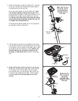
2. See the inset drawing. Remove the two M10 x 45mm

Button Bolts (33) and the packing tubes from the front

of the Frame (1). Next, remove the rubber band from

the Lower Wire Harness (87). Discard the Button

Bolts, the packing tubes, and the rubber band.

Press the two Stabilizer Endcaps (35) onto the Front

Stabilizer (3). Orient the Stabilizer Endcaps as shown.

35

3

1

33

2

Packing Tube

Packing

Tube

1

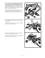
3. Slide an M10 Split Washer (94) onto each of the two

M10 x 83mm Button Screws (63). Insert the Button

Screws into the Front Stabilizer (3). Next, slide the

Mast (15) onto the Button Screws and against the

Front Stabilizer. Make sure that the Mast is oriented

as shown.

While another person holds the Mast (15) and the

Front Stabilizer (3) near the Frame (1), connect the

Extension Wire Harness (95) to the Lower Wire

Harness (87). Insert the connectors on the Wire

Harnesses into the Mast.

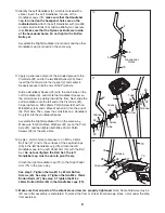
While the other person lifts the front of the Frame (1),

carefully pull the upper end of the Extension Wire

Harness (95) to remove any slack. While holding

the upper end of the Extension Wire Harness,

attach the Mast (15) and the Front Stabilizer (3) to the

Frame with the two M10 x 83mm Button Screws (63).

Do not tighten the Button Screws yet.

Make sure that the Wire Harnesses (87, 95) do not

get pinched and damaged during this step.

94

3

1

63

3

15

95

87

Pull

Make sure that the

wire harnesses do

not get pinched

and damaged

during this step.

87

35

Summary of Contents for PFEL4905.0

Page 1: ...ent Keep this manual for future reference Model No PFEL4905 0 Serial No _ Serial Number Decal QUESTIONS As a manufacturer we are com mitted to providing complete customer satisfaction If you have ques...

Page 2: ...SEMBLY 5 HOW TO USE THE ELLIPTICAL EXERCISER 10 MAINTENANCE AND TROUBLESHOOTING 15 CONDITIONING GUIDELINES 16 PART LIST 17 EXPLODED DRAWING 18 HOW TO ORDER REPLACEMENT PARTS Back Cover LIMITED WARRANT...

Page 3: ...than 250 pounds 8 Wear appropriate exercise clothes while using the elliptical exerciser Always wear athletic shoes for foot protection while using the elliptical exerciser 9 Hold the handgrip pulse...

Page 4: ...ions after reading this manual see the front cover of this manual To help us assist you please note the product model number and serial number before con tacting us The model number is PFEL4905 0 The...

Page 5: ...ntify small parts The number in parentheses below each drawing is the key number of the part from the PART LIST on page 17 The number following the parentheses is the quantity needed for assembly Note...

Page 6: ...into the Front Stabilizer 3 Next slide the Mast 15 onto the Button Screws and against the Front Stabilizer Make sure that the Mast is oriented as shown While another person holds the Mast 15 and the...

Page 7: ...tery door Reattach the battery door 5 5 Batteries Batteries Battery Cover Make sure the wire harnesses do not get pinched and damaged during this step 4 2 46 67 15 83 83 95 86 76 72 Hexagonal Holes 4...

Page 8: ...he same way 8 16 14 84 53 75 7 Slide the Right Crank Arm 38 onto the four indicated welded bolts make sure that the Right Crank Arm is in the indicated cutout in the Pedal Disk 8 Next finger tighten f...

Page 9: ...e Pivot Axle Slide a Handlebar Spacer 25 onto the short tube on the Left Handlebar 9 and rotate the Handlebar Spacer so the small arrow is pointing toward the floor Next slide the Left Handlebar onto...

Page 10: ...est pedal first Then step off the lowest pedal HOW TO USE THE HANDLEBARS The handlebars are designed to add upper body exer cise to your work outs Push and pull the handlebars as you exercise to work...

Page 11: ...gram see page 13 To use a preset program see page 14 Before using the console make sure that batteries are installed see assembly step 5 on page 7 If there is a sheet of clear plastic on the display r...

Page 12: ...r the most accurate heart rate reading continue to hold the handgrip pulse sensor for about 30 seconds Note If you continue to hold the hand grip pulse sensor the display will show your heart rate for...

Page 13: ...in the display instead of your heart rate Begin pedaling to start the program Pulse program 1 is 30 minutes long and is divided into several time periods of different lengths One target heart rate is...

Page 14: ...the display for a few seconds The resistance of the pedals will then automatically change to the resistance level that is programmed for the next period Note If the resistance level is too high or too...

Page 15: ...he result of low batteries See assembly step 5 on page 7 for replacement instructions HANDGRIP PULSE SENSOR TROUBLESHOOTING Avoid moving your hands while using the handgrip pulse sensor Excessive move...

Page 16: ...strengthen your cardiovascular sys tem your exercise must be aerobic Aerobic exer cise is activity that requires large amounts of oxygen for prolonged periods of time This increases the demand on the...

Page 17: ...5 2 Adjustment Knob 46 7 M8 Nylon Locknut 47 2 Crank Screw 48 2 Hub Cover 49 1 M6 x 8mm Screw 50 4 M8 x 45mm Button Bolt 51 1 Return Spring 52 1 Magnet Guide 53 6 M8 Washer 54 1 C Magnet 55 1 Motor 56...

Page 18: ...Model No PFEL4905 0 R0106B 46 2 6 9 10 11 22 23 91 67 53 71 71 24 15 74 22 23 24 53 91 27 28 27 86 79 46 50 24 25 26 24 89 81 87 72 76 27 28 28 79 27 5 50 46 24 25 26 24 89 7 66 66 74 66 66 66 74 74...

Page 19: ...29 75 18 18 38 88 45 19 17 20 93 65 92 42 42 80 8 21 40 47 57 80 92 14 18 18 88 45 42 42 20 19 17 36 93 65 47 57 40 21 48 82 66 53 66 66 53 53 66 16 84 84 43 1 78 69 66 77 66 29 55 61 62 90 90 62 49...

Page 20: ...anty does not extend to any product or damage to a product caused by or attributable to freight damage abuse misuse improper or abnormal usage or repairs not provided by an ICON authorized service cen...

Reviews: