background image

19

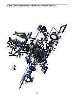
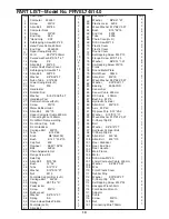
PART LIST—Model No. PFIVEL74514.0

Item

62

63

64

65

66

67

68

69

70

71

72

73

74

75

76

77

78

79

80

81

82

83

84

85

86

87

88

89

90

91

92

93

94

95

96

97

98

99

100

101

102

103

104

105

106

107

108

109

110

111

112

113

114

115

116

117

118

119

120

121

Description
Washer           Φ8*Φ21*2T

Plastic cover     8209

Wave Washer Φ19*Φ23*0.5T

Bush               Φ19*34*19      

End Cap         8209

Tube               8209

Chain Cover(L+R)

Drill Screw M5*15

Plastic Cover

Plastic Cover

Round Cover

Self-tapping Screw M4.5*10

Flange Screw  M10*1.25

Washer           Φ6*Φ14*1.5T

Self-tapping Screw M4*15

Crank

Round Metal Plate 

Belt Wheel      305J6

Allen Bolt       M6*10

Wave Washer Φ20*Φ25*0.5T

Washer          Φ20*Φ25*1T

Bearing          6004-2RS

Sensor Set 

Sensor Cable  600mm

DC Cable      400mm

Bushing   Φ13*5

Hydraulic Cylinder 

Allen Bolt       M8*100

Axis   Φ10*42

Oppress Pole   Φ37*20.5

Washer      Φ10*Φ15*1T

Wave Washer Φ10*Φ14*0.5T

C-Sharp Clip Φ8

Bolt

Washer      Φ8*Φ16*2T

Hydraulic Cylinder Bolt

C-Sharp Clip Φ6

Allen Bolt        M8*60

Allen Bolt        M8*110

Rear  Stabilizer

Rear  End Cap

Rear  Handle

Main Frame

Motor

Drill Screw M5*20

Lower Computer Cable  450mm

Washer          Φ8*Φ24*0.5T

Wire

Front Plastic Cover    

Rubber Ring

Washer          Φ20*Φ25*2T

C-Sharp Clip    Φ18

Self-tapping Screw M4.5*25 

Hexagon Wrench 5mm

Combination Wrench

Adaptor

Cable

Screw              M5*15

Nut                  M6

Connecting Wire 700mm

Qty.

2

2

2

4

4

2

1

5

2

2

2

4

2

8

8

2

2

1

4

1

1

2

1

1

1

2

1

1

1

1

2

1

1

1

3

1

1

2

2

1

2

1

1

1

7

1

2

1

1

1

1

1

4

2

1

1

1

2

4

1

Item

1

2

3

4

5

6

7

8

9

10

11

12

13

14

15

16

17

18

19

20

21

22

23

24

25

26

27

28

29

30

31

32

33

34

35

36

37

38

39

40

41

42

43

44

45

46

47

48

49

50

51

52

53

54

55

56

57

58

59

60

61

Description
Computer      355357

Screw              M5*12

Allen Bolt        M8*85

Computer Rack

Screw              M5*20

End Cap          Φ32

“Hand Grip       Φ32  

Self-tapping Screw M3.5*20 

Hand Pulse Cable  600mm

End Cap          Φ32xΦ50

Upper Swing Bar(L+R)

Form              Φ32*3T*630mm

Curved washer Φ8*Φ19*1.5T

Spring             Φ8

Allen Bolt        M8*20

Center Shaft Plastic Cover 

Self-tapping Screw M4*15

Allen Bolt        M8*20

Washer           Φ8*Φ36*3T

Nylon Tube     Φ19*Φ38

Lower Swing Bar(L+R)

Nut                  M8

Handle Bar

Rotation Rod

Washer           Φ19.5*Φ38*0.5T

Handlebar Post

Central shaft cover(F+R)

Screw              M5*15

Water Bottle Holder

Allen Bolt       M8*70

Upper Computer Cable 850mm

Connecting Wire 1250mm

Front Main Frame welding

Front End Cap    Φ65

Front Stabilizer

Carriage Bolt      M8*75

Tube                  Φ14.5*86

Knob                 M8*30(8103)

Bush                 Φ14.7*31.8*10

Cap Nut            M8

Flywheel          Φ245*105*32

Belt                  460J6

Chain Adjustable Set

Flange Screw 3/8

Axle Cap

Allen Bolt        M10*90

Bush               14*32

Tube               Φ14*72.2

Washer           Φ10*Φ19*2T

Nut                  M10

Footplate Support Bar (L+R)

Carriage Bolt      M6*55

Spring            Φ0.7*6.4*47

Pedal locker

Screw              M5*12

Rubber pad

Washer           Φ6*Φ14*2T

Spring             Φ6

Round Head Quick Pin M6

Footplate (L+R)

Allen Bolt       

Qty.

1

4

2

1

2

2

2

4

2

2

1

2

10

12

6

2

10

4

2

6

1

4

2

1

4

1

1

2

1

1

1

1

1

2

1

2

1

3

2

2

1

1

2

2

2

2

4

2

2

3

1

4

4

2

8

2

4

4

4

1

2

Summary of Contents for PFIVEL74514.0

Page 1: ...p this manual for future reference QUESTIONS If you have questions or if there are missing parts please contact us UK Call 08457 089 009 From Ireland 053 92 36102 Website www iconsupport eu E mail csu...

Page 2: ...FORE YOU BEGIN 4 WARNING DECAL PLACEMENT 4 ASSEMBLY 5 HOWTO OPERATETHE ELLIPTICAL 9 FEATURES OF THE CONSOLE 11 EXERCISE GUIDELINES 14 EXPLODED DRAWINGS 16 PART LIST 17 MAINTENANCEANDTROUBLESHOOTING 18...

Page 3: ...e sure that there is at least 3 ft 0 9 m of clearance in the front and rear of the elliptical and 2 ft 0 6 m on each side 6 Inspect and properly tighten all parts regu larly Replace any worn parts imm...

Page 4: ...te the product model number and serial number before contacting us The model number is PFIVEL74514 0 and the loca tion of the serial number decal are shown on the front cover of this manual Before rea...

Page 5: ...ssembly is completed In addition to the included tool s assembly requires an adjustable wrench and a Phillips screwdriver Use the part drawings below to identify the small parts used in assembly The n...

Page 6: ...nob under the bottom tube to keep it in Horizontal In this way make the bolt inserted smoothly STEP 2 Carefully lift the Handlebar Post 26 until it is verti cal Connect the Upper Computer Cable 31 and...

Page 7: ...the lower swing bar Left and Right 21 and secure in place using 4 Allen bolts 15 4 spring 14 and 4 curved washers 13 tighten fully III Fasten footplate support bars 51L R to the lower swing bars 21 wi...

Page 8: ...Do the same for the left pedal STEP 5 Secure Handle Bar 23L R with 2xM8Allen Bolt 3 Curved washer 13 and Nut 22 Connect two cables hand pulse cable 9 and connecting cable 121 then connect the upper c...

Page 9: ...te The elliptical exerciser does not have a free wheel the pedals will continue to move until the flywheel stops When the pedals are stationary step off the highest pedal first Then step off the lower...

Page 10: ...s are securely connected to the crank arms Finally put back the safety pin in its location You may have to force a bit to have it pulled in in place HOW TO MOVE THE ELLIPTICAL To move the elliptical f...

Page 11: ...sure your heart rate using the handgrip heart rate monitor The console also offers a selection of preset workouts Each preset workout automatically changes the resistance of the pedals as it guides yo...

Page 12: ...in to appear in succession The right display This display can show the distance you have pedaled in total revolutions and your pedaling speed in revolutions per minute rpm The display will change mode...

Page 13: ...flash The resistance level for the next segment will appear in the center display for a few seconds to alert you The resistance of the pedals will then change The target speed for the next segment wil...

Page 14: ...t allows you to view console usage information and to turn on or turn off the demo mode To select the settings mode press and hold down the Performance Workouts button for a few seconds until the sett...

Page 15: ...body uses carbohydrate calories for energy Only af ter the first few minutes of exercise does your body begin to use stored fat calories for energy If your goal is to burn fat adjust the intensity of...

Page 16: ...lles Stretch With one leg in front of the other reach forward and place your hands against a wall Keep your back leg straight and your back foot flat on the floor Bend your front leg lean forward and...

Page 17: ...eplace any worn parts immediately To clean the elliptical use a damp cloth and a small amount of mild detergent Important To avoid damaging the console keep liquids away from the console and keep the...

Page 18: ...6 27F 17 27R 11R 11L 28 29 30 14 15 33 34 35 40 13 38 36 37 49 48 47 46 50 51R 60R 51L 60L 69 70 71 72 73 79 76 75 85 84 69 38 99 18 14 68L Item 115 2 Item 116 21R 21L 77 88 54 55 22 89 110 22 78 31 1...

Page 19: ...2 2 4 2 8 8 2 2 1 4 1 1 2 1 1 1 2 1 1 1 1 2 1 1 1 3 1 1 2 2 1 2 1 1 1 7 1 2 1 1 1 1 1 4 2 1 1 1 2 4 1 Item 1 2 3 4 5 6 7 8 9 10 11 12 13 14 15 16 17 18 19 20 21 22 23 24 25 26 27 28 29 30 31 32 33 34...

Page 20: ...E U CUSTOMERS This electronic product must not be disposed of in municipal waste To preserve the environment this product must be recycled after its useful life as required by law Please use recycling...

Reviews: