background image

21

HOW TO USE AN IFIT LIVE WORKOUT

Note: To use an iFit Live workout, you must have an

optional iFit Live module.

To purchase an iFit Live

module at any time, go to www.iFit.com or call the

telephone number on the front cover of this man-

ual.

You must also have access to a computer with a

USB port and an internet connection. In addition, you

must have access to a wireless network including an

802.11b router with SSID broadcast enabled (hidden

networks are not supported). An iFit.com membership

is also required.

1. Insert the key into the console.

See HOW TO TURN ON THE POWER on page 17.

2. Insert the iFit Live module into the console.

To insert the iFit Live module, see the instructions

included with the iFit Live module.

3. Select a user.

If more than one user is registered, you can switch

users in the iFit Live main screen. Press the in-

crease and decrease buttons next to the Enter but-

ton to select a user.

4. Select an iFit Live workout.

To select an iFit Live workout, press one of the iFit

Live buttons. Before a workout will download, you

must add the workout to your queue on

www.iFit.com.

Press the iFit Live button to download the next

workout in your queue. Press the My Trainer but-

ton, the My Maps button, the World Tour button, or

the Event Training button to download the next

workout of that type in your queue. Press the

Compete button to compete in a race that you have

previously scheduled. For more information about

the iFit Live workouts, please see www.iFit.com.

Note: If there are no workouts of the selected type

in your queue, the next workout in your queue will

be downloaded.

When you select an iFit Live workout, the display

will show the duration of the workout, the distance

you will walk or run, the approximate number of

calories you will burn, and the name of the workout.

If you select a competition workout, the display will

count down to the beginning of the race.

Note: Each iFit Live button can also run two demo

workouts. To use the demo workouts, remove the

iFit Live module from the console and press one of

the iFit Live buttons.

5. Start the workout.

See step 3 on page 20.

During some workouts, the voice of an audio coach

will guide you through your workout. You can select

a setting for your audio coach (see THE INFORMA-

TION MODE on page 23).

To stop the workout at any time, press the Stop

button. The time will begin to flash in the display.

To resume the workout, press the Start button or

the Speed increase button. The walking belt will

begin to move at the speed setting for the first seg-

ment of the workout. When the next segment of the

workout begins, the treadmill will automatically ad-

just to the speed and incline settings for the next

segment.

6. Follow your progress with the displays.

See step 5 on page 18.

7. Measure your heart rate if desired.

See step 6 on page 19.

8. Turn on the fan if desired.

See step 7 on page 19.

9. When you are finished exercising, remove the

key from the console.

See step 8 on page 19.

For more information about the iFit Live mode, go to

www.iFit.com.

Summary of Contents for PFTL99910.0

Page 1: ...ual for future reference QUESTIONS If you have questions or if parts are damaged or missing DO NOT CON TACT THE STORE please contact Customer Care IMPORTANT Please register this product see the limite...

Page 2: ...is missing or il legible call the telephone number on the front cover of this manual and request a free replacement decal Apply the decal in the location shown Note The decals may not be shown at act...

Page 3: ...an extension cord 12 Use only a single outlet surge suppressor that meets all of the specifications described on page 15 To purchase a surge suppressor see your local PROFORM dealer or call the tele p...

Page 4: ...3 Never insert any object into any opening on the treadmill 24 Inspect and properly tighten all parts of the treadmill regularly 25 DANGER Always unplug the power cord immediately after use before cle...

Page 5: ...ore using the treadmill If you have questions after read ing this manual please see the front cover of this man ual To help us assist you please note the product model number and serial number before...

Page 6: ...Assembly requires the included hex keys and your own Phillips screwdriver adjustable wrench and scissors Use the drawings below to identify the assembly hardware The number in parentheses below each d...

Page 7: ...the power cord is unplugged Place a piece of cardboard below the rear of the Frame 56 to protect the floor or carpet Attach the Left Wheel Cap 96 to the Base 94 with two 8 x 3 4 Screws 2 Attach the R...

Page 8: ...pright 90 89 82 80 90 79 83 5 4 Hold the Left Upright 89 against the Base 94 Be careful not to pinch the Upright Wire 81 Insert two 3 8 x 1 1 4 Bolts 8 with two 3 8 Star Washers 13 and two 3 8 x 2 3 4...

Page 9: ...the same way 7 89 88 87 4 4 5 5 11 11 6 Cut the plastic tie in the Left Handrail 88 and the Right Handrail not shown If necessary press the 5 16 Cage Nuts 31 back into place Identify the Left Handrail...

Page 10: ...e Wire Wire Tie 88 81 81 Console Wire 8 Set the console assembly face down on a soft surface to avoid scratching the console assem bly Remove the two Screws A Next lift off the Crossbar 93 Discard the...

Page 11: ...nto the Left Handrail Attach the console assembly with six 8 x 1 2 Screws 1 and four 1 4 x 1 2 Bolts 36 with four 5 16 Flat Washers 113 and four 1 4 Star Washers 35 as shown Start all six Screws and a...

Page 12: ...the Left Upright 89 Attach the Left Upright Cover with three 8 x 1 2 Screws 1 Attach the Right Upright Cover 80 to the Right Upright 90 in the same way 14 89 1 Console Assembly 79 1 90 80 1 15 Attach...

Page 13: ...Frame 56 with a 3 8 x 1 3 4 Bolt 6 and a 3 8 Nut 12 Attach the lower end of the Storage Latch 53 to the Base 94 with a 3 8 x 2 Bolt 3 and a 3 8 Nut 12 Note It may be necessary to move the Frame 56 ba...

Page 14: ...ce a mat under the treadmill Note Extra hardware may be included Keep the included hex keys in a secure place one of the hex keys is used to adjust the walking belt see pages 26 and 27 18 Attach the R...

Page 15: ...power cord has an equip ment grounding conductor and a grounding plug Plug the power cord into a surge suppressor and plug the surge suppressor into an appropriate outlet that is properly installed an...

Page 16: ...module at any time go to www iFit com or call the telephone number on the front cover of this manual You can also connect to Nikeplus com through the op tional PROFORM SYNC With the SYNC you can use a...

Page 17: ...of mea surement is selected see THE INFORMATION MODE on page 23 For simplicity all instructions in this man ual refer to miles HOW TO USE THE MANUAL MODE 1 Insert the key into the console See HOW TO...

Page 18: ...treadmill changes The Time display This display will show the elapsed time Note When an onboard workout is selected the display will show the time remaining in the workout instead of the elapsed time...

Page 19: ...ss the Fan increase or decrease button to select a fan speed or to turn off the fan Note If the fan is on when the walking belt is stopped the fan will turn off auto matically after a few minutes 8 Wh...

Page 20: ...If a new speed and or incline setting is pro grammed for the next segment the new speed and or incline setting will appear in the displays for a few seconds and the treadmill will automatically adjust...

Page 21: ...or more information about the iFit Live workouts please see www iFit com Note If there are no workouts of the selected type in your queue the next workout in your queue will be downloaded When you sel...

Page 22: ...y music or audio books through the console s stereo speakers you must connect your iPod MP3 player CD player or other personal audio player to the console through the audio jack or through the optiona...

Page 23: ...display will show the con trast level of the displays Press the Incline increase and decrease buttons to adjust the contrast Then press the Enter button If a module is connected the information mode...

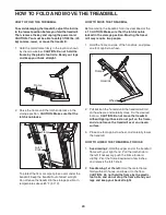
Page 24: ...latch knob is locked in the storage position Moving the tread mill may require two people 1 Hold the frame and one of the handrails and place one foot against a wheel 2 Pull back on the handrail unti...

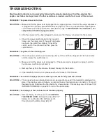
Page 25: ...ng use SOLUTION a Check the power switch see the drawing above If the switch has tripped wait for five minutes and then press the switch back in b Make sure that the power cord is plugged in If the po...

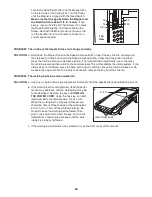
Page 26: ...rate the incline system If the incline does not calibrate press the Stop button again and then press the Incline increase or de crease button again When the incline is calibrated remove the key from t...

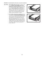
Page 27: ...en plug in the power cord insert the key and run the treadmill for a few minutes Repeat until the walking belt is centered b If the walking belt slips when walked on first re move the key and UNPLUG T...

Page 28: ...our goal is to strengthen your cardiovascular system you must perform aerobic exer cise which is activity that requires large amounts of oxygen for prolonged periods of time For aerobic ex ercise adju...

Page 29: ...les Stretch With one leg in front of the other reach forward and place your hands against a wall Keep your back leg straight and your back foot flat on the floor Bend your front leg lean forward and m...

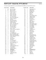
Page 30: ...r Isolator Top 39 4 Isolator 40 4 Isolator Bottom 41 1 Right Front Isolator Top 42 1 Left Foot Rail 43 1 Caution Decal 44 1 Walking Platform 45 1 Walking Belt 46 2 Belt Guide 47 2 Foot Rail Track 48 4...

Page 31: ...Console Clamp 107 1 Left Tray 108 1 Right Tray 109 1 Console Base 110 1 Base Ground Wire 111 3 Hood Clip 112 2 10 x 3 4 Flat Head Screw 113 4 5 16 Flat Washer User s Manual Note Specifications are su...

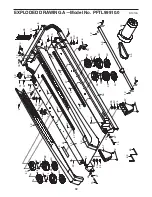
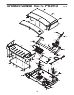
Page 32: ...8 54 40 39 41 40 39 38 2 2 37 2 2 39 38 40 40 39 42 44 60 47 2 47 34 30 59 34 30 34 30 23 30 34 57 64 57 2 52 55 6 12 3 46 19 50 14 51 21 21 27 26 35 45 2 2 2 12 2 14 14 14 14 2 2 2 2 2 2 10 10 48 59...

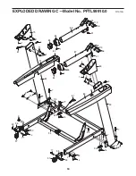
Page 33: ...10 76 77 74 2 111 111 111 75 10 2 2 73 33 69 67 71 16 33 70 67 71 65 1 1 19 29 1 32 32 68 72 74 2 2 2 78 19 19 28 28 22 22 28 62 14 2 2 2 14 58 2 2 2 2 2 EXPLODED DRAWING B Model No PFTL99910 0 R1010A...

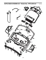
Page 34: ...17 97 96 33 92 92 7 13 8 90 77 7 13 4 80 87 86 84 85 84 4 11 5 79 81 81 31 88 1 82 83 14 92 8 1 1 1 2 33 1 1 10 11 5 91 91 110 97 14 14 14 33 33 7 7 36 35 113 36 35 113 34 EXPLODED DRAWING C Model No...

Page 35: ...98 100 93 1 1 107 108 109 25 25 106 106 104 105 10 1 2 101 102 103 2 2 2 2 2 2 1 1 1 2 99 2 1 1 1 1 1 9 35 112 9 35 112 35 EXPLODED DRAWING D Model No PFTL99910 0 R1010A...

Page 36: ...trip charge This warranty does not extend to any damage to a product caused by or attributable to freight damage abuse misuse improper or abnormal usage or repairs not provided by an ICON authorized s...

Reviews: