


22
1
1
Frame
2
1
Upright
3
1
Console
4
5
M10 x 22mm Screw
5
1
Fan
6
1
Seat Post
7
1
Left Handlebar
8
1
Left Handlebar Base
9
1
Right Handlebar
10
1
Right Handlebar Base
11
2
Foam Grip
12
2
Handlebar Cap
13
1
Left Guard
14
1
Right Guard
15
1
Left Link Arm
16
1
Right Link Arm
17
1
Left Shield
18
1
Right Shield
19
1
Front Stabilizer
20
1
Seat
21
2
Stabilizer Cap
22
1
Belt
23
2
Pedal
24
2
Handlebar Base Cap
25
1
Pulley
26
2
Crank Arm
27
2
M4 x 13mm Flange Screw
28
2
Frame Bearing
29
1
Seat Knob
30
2
Guard Bracket
31
1
Reed Switch/Wire
32
1
Clamp
33
1
Handlebar Axle
34
6
Handlebar Bushing
35
2
Guard Fastener
36
1
Fan Axle
37
2
Fan Bearing
38
2
Adjustment Bracket
39
1
Extension Wire
40
1
Idler Arm
41
2
Crank Cap
42
2
Pedal Spring
43
2
Pedal Bushing
44
2
Pedal Spacer
45
2
Link Arm Bushing
46
1
Seat Post Guide
47
1
Seat Post Bushing
48
2
Magnet
49
2
Axle Cover
50
2
Axle Cap
51
2
Fan Washer
52
2
Eyebolt
53
2
M6 Nut
54
3
M10 Split Washer
55
3
M10 x 17mm Screw
56
4
M6 Locknut
57
4
M6 x 38mm Bolt
58
2
M8 x 74mm Bolt
59
1
M10 x 18mm Flat Head Bolt
60
1
Rear Stabilizer
61
1
M4 x 13mm Screw
62
4
M4 x 16mm Round Head Screw
63
2
Footrest Cover
64
1
M10 Locknut
65
2
M10 x 65mm Screw
66
10
M8 Locknut
67
2
Flange Screw
68
2
1/2" Pedal Nut
69
9
M4 x 25mm Screw
70
1
M4 x 5mm Screw
71
2
Red Washer
72
8
M8 Split Washer
73
4
M8 Flat Washer
74
1
Fan Spacer
75
1
Idler Spring
76
5
Guard Clip
77
5
M4 x 16mm Screw
78
2
Wave Washer
79
2
Black Pedal Washer
80
1
Ground Wire
81
4
M8 x 20mm Bolt
82
1
Crank
83
2
Snap Ring
84
2
M8 x 16mm Screw
85
2
M8 Washer
86
2
Custom Washer
87
2
Pulse Grip
88
2
Wheel
89
2
Shoulder Screw
*
–
Assembly Tool
*
–
User’s Manual
Key No. Qty.
Description
Key No. Qty.
Description
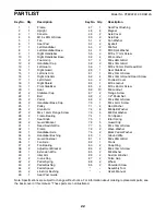
Note: Speci
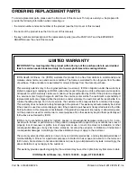
cations are subject to change without notice. For information about ordering replacement parts, see
the back cover of this manual. *These parts are not illustrated.
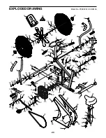
PART LIST
Model No. PFEX22912.0 R0812A
Summary of Contents for XP Whirlwind 320
Page 21: ...21 NOTES...


