


© Pro-Ject Audio Systems · Pro-Ject RPM 9 Carbon · Revision 2015.07.10
6
Adjusting the azimuth
The cartridge needle must be vertical in the record groove in order to trace
the groove wall modulations correctly.
A small screw at the bearing end of the arm allows incorrect azimuth to be
corrected.
Slacken off the screw just enough to be able to revolve the arm tube
without applying force. Note! Do not remove this screw completely!
Screw
With the aid of a good magnifying glass adjust the needle until it is vertical in the groove (i.e.
perpendicular to the record's surface). Ideally this should correspond to the top surface of the
cartridge body being parallel to the record surface.
When the needle is vertical, retighten the screw carefully.
!
Under no circumstances should the arm tube be adjusted with the needle still in the record
groove! Irreparable damage may be caused to the cantilever suspension! The arm must be lifted
to make each adjustment and lowered afterwards to check it.
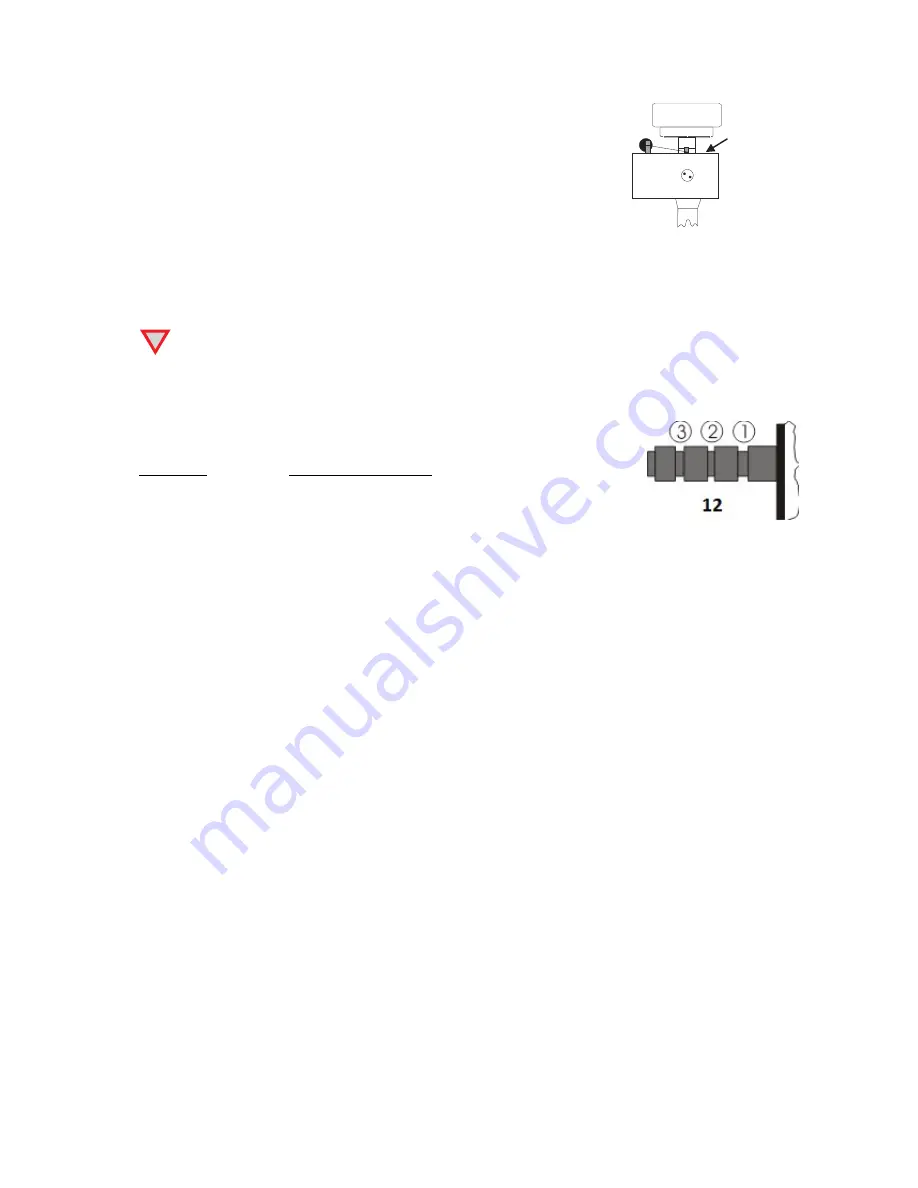
Anti-skating force adjustment
The anti-skating force must be adjusted corresponding to the downforce as
follows:
Downforce
Groove in the stub (15)
10 - 14mN
1
st
from bearing rings
15 - 19mN
2
nd
" " "
20mN and bigger
3
rd
" " "
Hang the loop of the thread of the anti-skating weight into the groove of the anti-skating stub (12)
corresponding to the downforce applied to your cartridge and hang the thread into the groove of the
wire support (14).
Connection to the amplifier
The record player uses an output through a 5 PIN connector (11). Use supplied
Pro-Ject Connect IT 5P-
CC
cable to connect the turntable to the amplifier.
Use the Phono input (sometimes labelled gram, disc or RIAA) on your amplifier. Make sure that the
phono input offers correct matching and amplification for the type of cartridge used. Line inputs (like
CD, Tuner, Tape or Video) are not suitable.
Take care about connecting the left and right channel correctly. The right channel is usually marked
red, the left channel black or white. Check the manual of your amplifier for relevant information. An
earthing wire may be connected to the screw terminal between the sockets if you encounter humming
problems.
If your amplifier does not have an input suitable for phono cartridges, a separate phono amplifier
stage for MM or MC cartridges is required. It has to be connected between record player and a free
line level input of the amplifier.
For detailed product information regarding Pro-Ject Audio Systems interconnect cables and phono
amplifiers please visit our website:
www.project-audio.com
Mains power connection
A universal power supply with 3 exchangeable sockets adapters suitable for all countries is supplied.
Select the correct adapter for your country and insert the adapter to the exchangeable part of the
power supply.
Connect the low voltage plug from the power supply to the socket (10) on the rear side of the record
player before
connecting the power supply to the mains.


