V1.0
180 MULTI-PROCESS MIG-ARC-TIG WELDER
8611311
Visit www.princessauto.com for more information
13
3. Set the welding current relevant to the
electrode type and size being used, as
recommended by the electrode
manufacturer (Fig. 5)
4. Place the electrode into the electrode
holder and clamp tight (Fig. 6)
I
NSTALLATION &
OPERATION FOR MIG WITH GAS
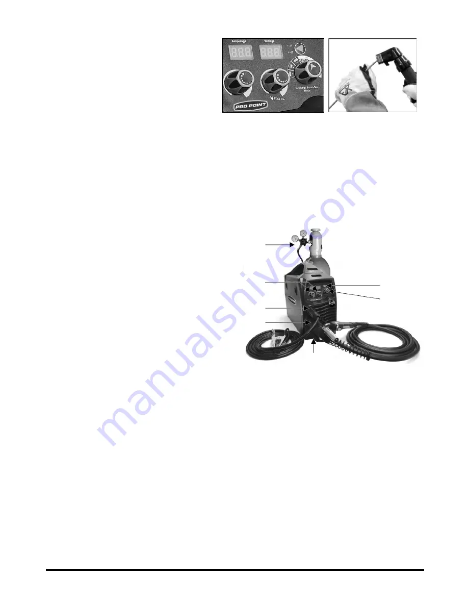
1. Connect the MIG Torch to the Euro connector (H) and tighten the connector (Fig. 7-1).
2. Connect the ground lead to negative output socket (G) (Fig. 7-2).
3. Connect the weld power lead to positive outlet socket (I) (Fig. 7-3).
4. Install the welding wire if needed (See Wire Installation and Setup).
5. Open the valve on the gas cylinder and set the flow to 21 CFH (Fig. 7-4).
6. Turn the power source on and select the MIG function with the welding mode knob. An
alternative is to use the Smartset option
(see Smartset) (Fig. 7-6).
7. Set torch operation 2T / 4T (Fig. 7-5).
• 2T - Press and hold the trigger to start
the arc. Release the trigger to stop.
• 4T - Press and release the trigger to
start the arc. Press and release the
trigger to stop the arc.
The burnback function is automatic and
preset for both selections.
8. Set the welding parameters using the wire
feed (D) and voltage control knobs (E).
These will already be set if Smartset was
selected (Fig. 7-7).
I
NSTALLATION & OPERATION FOR GASLESS MIG
1. Connect the MIG Torch to the Euro connector (H) and tighten the connector.
2. Connect the ground lead to the positive output socket (I).
3. Connect the weld power lead to the negative outlet socket (G).
4. Install flux-cored welding wire and the knurled drive roller (see Wire Installation and Setup).
5. Turn the power source on and select the MIG function with the welding mode knob.
6. Set torch operation 2T / 4T.
• 2T - Press and hold the trigger to start the arc. Release the trigger to stop.
• 4T - Press and release the trigger to start the arc. Press and release the trigger to stop
the arc.
The burnback function is automatic and preset for both selections.
7. Set the welding parameters using the wire feed (D) and voltage control knobs (E). These
will already be set if smartset was selected.
7-4
7-2
7-1
7-5
7-7
7-3
7-6
Fig. 7
Fig. 5
Fig. 6


