ARC 1 8 5 0
PRO
WEL D
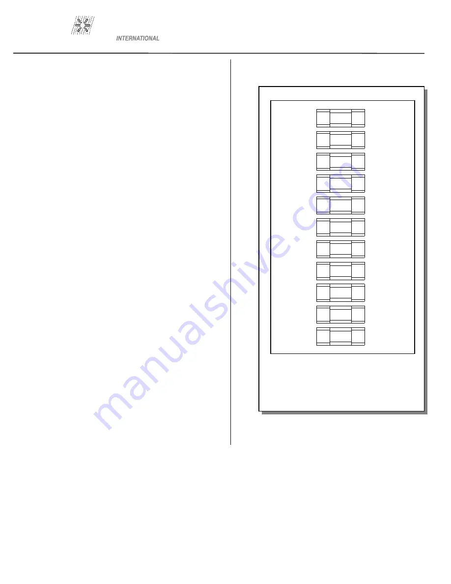
Figure 4
FUSE BLOCK
(Dual gun version shown)
F12
F11
F10
F9
F8
F7
F6
F5
F4
F3
F2
25 AMP
SLO BLO
5 AMP
CERAMIC
1 AMP
1 AMP
1 AMP
1 AMP
1 AMP
25 AMP
SLO BLO
25 AMP
SLO BLO
1 AMP
1 AMP
8.2 Checking Gun Lift
To measure lift, turn the stud welding unit on and set the timer to
maximum time. (On certain units there may be a Lift
Check switch available, and in these cases this switch can be used
to check lift.) Trigger the gun in the air, or on a
non-grounded or insulated surface, to observe the lift cycle. Meas-
uring the distance the stud or gun mechanism
moves equals lift - usually this can be easily done by visual obser-
vation or simple measurement against a static ref-
erence point (i.e. the ferrule properly seated in the ferrule grip).
Recommended Lift Settings.
Stud Base Dia. Lift Setting
Less than 1/2” 1/16”
1/2” through 3/4” 3/32”
Greater than 3/4” 7/64”
When it does become necessary to adjust lift, you do so by re-
moving the rear cap from the gun. This will expose the
rear coil yoke assembly, the set screw and the lift adjusting screw
(Loosen the set screw to avoid damaging the threads
of the lift adjusting screw).
To increase lift: turn the lift adjusting screw out (counter clock-
wise).
To decrease lift: turn the lift adjusting screw in (clockwise).
Once the lift has been set, tighten the set screw and replace the rear
cap.
PAGE 6
Summary of Contents for ARC 1850
Page 1: ...OPERATION MAINTENANCE MANUAL ...
Page 2: ......
Page 4: ...ARC 1850 PRO WELD ...
Page 5: ...ARC 1850 PRO WELD ...
Page 6: ...ARC 1850 PRO WELD ...
Page 7: ...ARC 1850 PRO WELD ...
Page 23: ......


