background image

Summary of Contents for XW-IS4

Page 1: ...XW IS4 XW IS4 Intercom System Intercom System ...

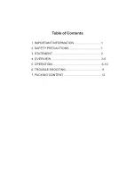
Page 2: ...Table of Contents 1 IMPORTANT INFORMATION 1 2 SAFETY PRECAUTIONS 1 3 STATEMENT 2 4 OVERVIEW 3 5 5 OPERATION 6 9 6 TROUBLE SHOOTING 10 7 PACKING CONTENT 11 ...

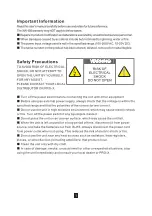
Page 3: ... the unit with other equipment Before using an external power supply always check that the voltage is within the specified range and that the polarities of the connector are correct Do not use the unit in high moisture environment which may cause electric shock or fire Turn off the power switch if any liquid gets inside it Do not place the unit on an uneven surface which may cause the unit fall Wh...

Page 4: ...ent nearby With other devices working under the similar frequency nearby Introduction XW IS4 is a Full Duplex wireless Intercom system It s designed for operation of live show program production broadcast and other applications where wireless communication is required It features advanced digital wireless and Audio Codec technology to allow the director camerapeople and control room communicate wi...

Page 5: ...All Channels Volume Control of Headphone Speaker from Minimum to Maximum Built in Speaker 5V DC Output V H V H 2 WIRE INPUT OUTPUT AUX AUDIO INTERCOM Red LED GND CH 1 2 3 4 1 2 3 4 NC NC Green LED TALLY MODE H L FREQ 1 8G 1 9G Red LED GND CH 1 2 3 4 1 2 3 4 NC NC Green LED AC Input DC Input Tally Active high and Active low DIP Switch Whentheleverisatupper location Tallysignalisin active high Whent...

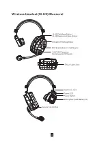
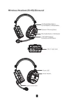
Page 6: ... Working Status 1 9G 1 8G Frequency Points Selector DIP Switch MIC Enable Button in Half Duplex IS HS Calls Base Station IS HS Registers on Base Station TALLY Light Jack Volume Control Dial Power Switch Power LED Battery Box AAA Battery 3 Earphone Jack 4 ...

Page 7: ... Knob MIC Enable Button in Half Duplex LCD Tally LED Tally Output Headphone Jack Battery Box AA Battery 3 or Nokia BL 5C Lithium ion Battery 1 9G 1 8G Frequency Points Selector Switch Belt Pack Calls Base Station Belt Pack Registers on Base Station Power Switch Antenna 5 ...

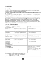
Page 8: ...with magnetic force There s one screw hole on antenna installation board which makes it easy to be installed on your equipment stand Full Duplex Half Duplex IS HS IS BP Calls Base Station Mute Mode Registered Base Station powered off IS HS IS BP powered on Unregistered IS HS IS BP Powered on Remarks Flash quickly 200ms ON 200ms OFF Flash slowly 500ms ON 500ms OFF Flash 3s OFF 1s ON Base Station st...

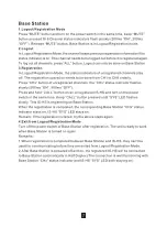
Page 9: ...LL button pressed until SYS LED flashes slowly This IS HS is registering on Base Station For IS BP press and hold Call button on an unregistered IS BP and turn on the power switch in the same time Keep Call button pressed until LCD displays Registering This IS BP is registering on Base Station When the registration is completed the corresponding Base Station CHx status indicator stays on IS HS SYS...

Page 10: ...ff voice enable function Intercom Operation Indications 2 Wire 4 Wire Intercom Operation and indications 1 4 Wire is on by default when Base Station is turned on Press 2W 4W button to enable 2 Wire Audio channel including Audio input output and 4 Wire Audio channel will be shut off Base Station communicates with other equipments in Full Duplex Any active channel is included in intercom Connector 3...

Page 11: ...n is able to press IS HS CALL button IS BP Call button to call Base Station Base Station CHx status indicator will flash quickly 200ms ON 200ms OFF IS HS SYS LED will flash quickly 200ms ON 200ms OFF IS BP LCD will display Call Press Base Station corresponding CHx button to allow the IS HS IS BP come into Full Duplex intercom Remarks 1 When a IS HS IS BP is mute by pressing corresponding CHx butto...

Page 12: ...uxiliary Level IN dial of Base Station Audio Electrical Level 1Vpp Auxiliary Audio Output When any channel is active Audio signals collected in Base Station output from this Auxiliary port The Auxiliary output signal electrical level can be adjusted via Auxiliary Level OUT dial of Base Station Audio Electrical Level 1Vpp IS HS IS BP Registration Refer to Log out Registration of Base Station Under ...

Page 13: ...the power switch is on 2 Check if installation of IS HS IS BP batteries is right 3 Check if batteries are exhausted 1 Check if Tally indicator plug is inserted in the socket well and steady 2 If the set works with a Switcher check if the connection of cables is correct 1 Check if IS HS IS BP is registered on Base Station 2 Check if the set work on the same frequency point 3 Check if the battery po...

Page 14: ...ension Cord forAntenna 1 5m AC Power Cord AC SMAM SMAFExtensionCord 5m BaseStation Back Panel Antenna Installation Board User s Manual 3 5 11P Connector No 1 2 3 4 5 6 7 8 9 10 11 12 13 14 Quantity 1 1 4 1 Set 4 1 4 1 1 4 1 1 1 Remarks Optional Optional One set for each IS BP XW IS4 Base Station AC Power Cord IS HS IS BP USB Charger Micro USB Cable 12 Extension Cord for Antenna 1 5m 3 5 11P Connec...

Page 15: ......

Page 16: ......

Page 17: ......

Page 18: ......

Page 19: ......

Page 20: ......

Page 21: ......

Page 22: ......

Page 23: ......

Page 24: ......

Page 25: ......

Page 26: ......

Page 27: ......

Page 28: ......

Page 29: ......

Page 30: ......

Reviews: