OFT-3 User's Guide Rev A 2/7/14
20
Least Squares Approximation (LSA)
Least Squares Approximation (LSA) Splice loss method gives the user a visual aid in setting splice loss areas.
This method can be more accurate by affording the ability to see the slope of the splice loss areas, however:
it can also supply a reading with greater error if not used properly. The splice loss lines must be set to overlay
the backscatter of a trace without over lapping any other events. Unlike basic splice lose, LSA measurement
areas are drawn as straight lines without regard to the undulations of the back scatter
7.10 Loss Measurement Settings
Basic Splice Loss
Splice Loss method is meant to be used in noisy environments when it is difficult to attain an LSA area that
lays flat on the back scatter before and after the cursor. This method takes an average of the selected points
before and after the active cursor and uses this average to make a good estimation of the event loss. This is an
estimation but this method may be more accurate than LSA Splice Loss method in noisy environments.
When using the splice loss It is necessary to set these areas in clear backscatter (areas that do not consist of
other events) to acquire the most accurate measurements. For accurate measurements, these areas can not
include other events such as reflective or splice events. Set a cursor at the beginning of an event and set splice
loss measurement areas as directed below for accurate splice loss measurements. Splice loss measurement
areas will follow the undulations of the back scatter line unlike LSA areas.
Chapter 7 OTDR Operation
Touch Screen Tip
The loss measurement/LSA areas may only be set with the key pad. Use the menu to enter the LSA settings
function, but once there, use the key pay to adjust the areas as described.
Setting Splice Loss Measurement Areas
To set the basic splice loss measurement/ LSA ares, the OTDR must be in Splice AVG or Splice LSA mode.
To adjust the splice loss areas around the cursors, press the menu button, highlight the LSA icon and press
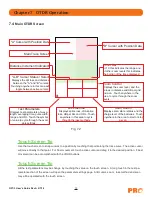
select. The splice lose position indicator will be displayed at splice loss position number 1 as indicated in Fig.
7.4. Use the left and right buttons to adjust the loss measurement area. Press the select button to move the
splice lose position indicator to the position number 2, set the area and continue with positions 3 and 4 in the
same manner. Press select when done with position number 4 to hide the splice lose position indicator and
reset the focus of the keyboard back to the cursors. Press the menu button at any time to escape the splice
lose settings sequence.
Note
It is necessary to set these areas in clear backscatter to acquire the most accurate measurements, they
must not include other events.


