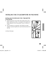
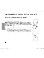
background image

4

english

WARNINGS & CAUTIONS

s 7!2.).'

 Failure to pay attention to the road, trail, traffic or your surroundings 

could result in an accident, with risk of serious injury, paralysis or death. You must 
focus on riding, not your computer. Learn computer operations, and do all possible 
computer operations when not riding. For any operations you choose to perform while 
riding, choose a time and place where this distraction has less risk. 

s #!54)/.

 Mount the Cyclecomputer according to the directions in this instruction 

manual.

s #!54)/.

 Avoid direct impact to the Cyclecomputer unit.

s #!54)/.

 Do not submerge the Cyclecomputer unit.

s #!54)/.

Avoid using the Cyclecomputer unit in or near strong electromagnetic fields 

such as high-voltage power lines or other transmitters.

s #!54)/.

 Do not disassemble the unit.

s #!54)/.

Make sure the magnet and the transmitter are well aligned and check them 

regularly.

s #!54)/.

PRO Scio Cyclecomputers are intended for use on bicycles only and should 

not be used on any motorized vehicle.

s #!54)/.

 Change the battery prior to failure to avoid data loss.

s #!54)/.

 Clean the unit with a mild detergent and a soft dry cloth. Never use any 

kind of solvent or alcohol.

o33_35_41_eng.indd   4

11/21/07   12:25:27 P

Summary of Contents for SCIO 3.3

Page 1: ...ENGLISH PRO SCIO s s o33_35_41_eng indd 1 11 21 07 12 25 26 P...

Page 2: ...8 WEARING THE HEART RATE TRANSMITTER STRAP 9 INSTALLING THE CYCLOCOMUTER ON YOUR BIKE 10 14 PRO SCIO SERIES DISPLAY FIELDS 15 MAIN OPERATING MODES 16 17 MEASURING WHEEL SIZE 18 19 PROGRAMMING THE CYC...

Page 3: ...MODE 33 RESETTING THE UNIT 33 SELECT BIKE 1 OR BIKE 2 34 DISTANCE TRAVELED DISTANCE COUNTDOWN 35 OPERATING THE STOPWATCH 36 VIEWING LAP DATA 37 TEMPERATURE MODE 38 CADENCE MODE PRO SCIO 3 3 39 HEART R...

Page 4: ...struction manual s 54 Avoid direct impact to the Cyclecomputer unit s 54 Do not submerge the Cyclecomputer unit s 54 Avoid using the Cyclecomputer unit in or near strong electromagnetic elds such as h...

Page 5: ...9 054 2 5 4 7 2 33 2 42 3 44 2 7 4 0 4 3 7 2 33 2 42 3 44 2 5 4 0 7 2 33 5 4 2 4 PRO SCIO 3 5 4 1 5 4 2 4 25 2 0 7 2 42 3 44 2 5 4 2 4 PRO SCIO 3 3 24 2 4 42 3 44 2 342 0 PRO SCIO 4 1 1 2 3 4 7 6 5 8...

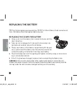
Page 6: ...ery compartment with the posi tive side toward the battery door Be extremely careful not to bend the battery contact when inserting a new battery 4 Place the battery door over the opening and tighten...

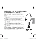
Page 7: ...emove the old battery 3 Place a new battery in the transmitter positive side toward the battery door 4 Place the battery door over the opening and tighten it down by using a coin and turning in a cloc...

Page 8: ...ompartment with the positive side toward the battery door 4 Place the battery door over the opening and tighten it down by using a coin and turning in a clockwise direction 5 If the O ring has been da...

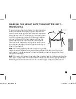
Page 9: ...mitter ts tightly below the pectoral muscles as shown in the drawing 4 Users with signi cant chest hair may have a problem obtaining contact between the transmitter electrodes and their skin resulting...

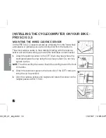
Page 10: ...p toward the handlebar or stem bracket 1 Attach the cadence sensor to the LEFT chain stay near where the crank pedal pass the stay using the zip ties provided Do not fully tighten zip ties 4 The wires...

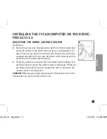
Page 11: ...e should be wrapped around the front or rear derailleur cable housing and the around the front brake cable housing Wrap any excess wire around the front brake cable housing Use electrical tape to secu...

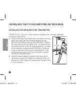
Page 12: ...rd Snug up the zip ties but do not fully tighten them The sensor should be mounted as high on the fork blade as possible The range of the transmitter is approximately 18in 46cm Mounting it high on the...

Page 13: ...and magnet so they are in proper alignment as shown The magnet should pass by the sensor adjacent to the molded plastic line at a distance of 1 3mm 4 Once everything is in alignment fully tighten the...

Page 14: ...back of the mounting bracket and rotate it 90 degees Replace the screws do not overtighten The unit is now properly aligned for mounting on the stem 2 Place the mounting bracket in the desired positi...

Page 15: ...44 29 4 2 7 2 30 9 Displays information speci c to current operating mode 5 43 ILES OR ILOMETERS 24 2 4 PRO Scio 4 1 Indicates Heart Rate signal received 4 0 2 452 30 34 2 2 4 5 4 Indicates current o...

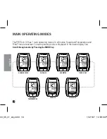
Page 16: ...operating modes In all modes Speed and Temperature and Ride Time are constant Current operating mode is displayed in the lower display line 3CROLL THROUGH MODES BY 0RESSING THE KEY 6 8 30 34 4 2 4 9 8...

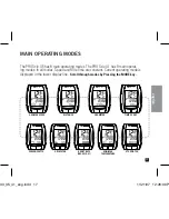
Page 17: ...1 has 9 main operat ing modes In all modes Speed and Ride Time are constant Current operating mode is displayed in the lower display line 3CROLL THROUGH MODES BY 0RESSING THE KEY 6 8 30 0 7 2 7 443 3...

Page 18: ...ogrammed wheel tire sizes Simply select the size of your tire as you scroll through the list in the programming sequence If your wheel tire size is not one of the sizes in the accompanying chart or if...

Page 19: ...your tire and the oor exactly where they meet 2 Roll your bike forward one full revolution of the front wheel and mark the point on the oor where the revolution is complete For maximum accuracy be si...

Page 20: ...Setting Menu There are 5 individual elds of information in the Odometer Setting Menu Scroll through the elds by Pressing the OPTION or EL key OTE you may exit the Setting Sequence at any time by Pres...

Page 21: ...ing the OPTION or EL key Set Units by Pressing the MODE key Advance to next setting option by pressing OPTION or EL key PROGRAMMING THE CYCLECOMPUTER ADJUST PRESS OPTION OR EL SELECT PRESS MODE SET PR...

Page 22: ...MODE key 3 Scroll through pre programmed wheel values by pressing the OPTION or EL key 4 Set wheel size by pressing the MODE key PROGRAMMING THE CYCLECOMPUTER SELECT PRESS MODE ADJUST PRESS OPTION OR...

Page 23: ...n to ash 7 Adjust digit by Pressing OPTION or EL key Set value and advance to next digit by Pressing the SELECT key 9 Once all elds have been adjusted Press the MODE key to return to Setting Menu 10 T...

Page 24: ...y pressing the OPTION or EL key 2 Press the MODE key The far right digit will begin to ash 3 Adjust digit by Pressing OPTION or EL key Set value and advance to next digit by Pressing the MODE key 5 On...

Page 25: ...format and advance to set time by Pressing the MODE key Adjust Hour by pressing the OPTION key to increase or the EL key to decrease 5 Set Hour and advance to set minutes by Pressing the MODE key 6 Ad...

Page 26: ...gle between Distance Up and Down The Distance Countdown icon will appear in the center line of the display 2 In Distance Down mode Press Hold the MODE key to enter the Programming Sequence 3 Adjust di...

Page 27: ...to calculate Power Wattage PRO Scio 3 5 4 1 only In Stopwatch Mode press hold the Mode key to enter the Setting Menu There are 2 individual elds of information in the Stopwatch Setting Menu Scroll th...

Page 28: ...bs or KG by pressing the OPTION or EL key Press MODE to set 4 Adjust Weight by pressing the OPTION or EL keys Press MODE to set 5 Select Gender by pressing the OPTION or EL keys 6 Press MODE to set re...

Page 29: ...the Stopwatch Setting menu select LAP by pressing the OPTION or EL key 2 Press the MODE key 3 Scroll through Lap functions AUTO or MANUAL by pressing the OPTION or EL key MANUAL FUNCTION To operate t...

Page 30: ...CE BASED LAPS Adjust distance 5 18 5 miles 30 km by pressing the OPTION or EL key Press the MODE key to return to operating mode SETTING TIME BASED LAPS 4 Adjust minutes by pressing the OPTION or EL k...

Page 31: ...e Viewing Lap Data page 37 In Heart Rate mode press hold the Mode key to enter the setting sequence Adjust UPPER LIMIT by pressing OPTION or EL key 3 Press the Mode key to set and advance to next sett...

Page 32: ...y to enter the setting sequence Select above or below Sea Level by pressing the OPTION or EL key 3 Press the Mode key to set and advance to next setting The far right digit will begin to ash Adjust di...

Page 33: ...the unit goes into SLEEP mode The display reads Time of Day in the center display line All other display elds are blank Press any key to wake the unit and resume Operating mode RESETTING THE UNIT To c...

Page 34: ...deter 2 Release the OPTION key to resume Bike 1 settings 2 Continue holding the OPTION key and press the SELECT key Bike 2 indicator icon will now display SWITCH FROM BIKE 2 TO BIKE 1 1 In Odometer OD...

Page 35: ...T key The center line display segments will display the relative distance remaining to your destination by varying display from right to left 2 The unit also estimates your Arrival Time based on your...

Page 36: ...of display screen AUTO TIMING LAPS In AUTO LAP setting laps are automatically timed by either a preset distance or time Current lap number is displayed in lower left of display screen and indicated a...

Page 37: ...scending order by pressing the OPTION key Lap data will automatically display in the following sequence 3 Press SELECT to resume timing Press MODE to exit data recall and resume normal operating mode...

Page 38: ...URE MODE Change Temperature units from C Celsius to F Fahrenheit by pressing holding the MODE key in Temperature mode OPERATING THE CYCLOCOMPUTER PRESS HOLD MODE PRESS HOLD MODE o33_35_41_eng indd 38...

Page 39: ...E MODE PRO SCIO 3 3 In Cadence mode toggle between Current Cadence and Average and Max cadence by pressing the OPTION key OPERATING THE CYCLOCOMPUTER PRESS OPTION PRESS OPTION o33_35_41_eng indd 39 11...

Page 40: ...VERAGE AND MAX HEART RATE Press the OPTION key in Heart Rate mode CONSTANT HEART RATE DISPLAY The PRO Scio 4 1 allows you to view current Heart Rate in all operating modes 1 In Heart Rate Mode press h...

Page 41: ...eter modes by pressing the OPTION key POWER MODE PRO SCIO 3 5 4 1 The PRO Scio displays your current Power Wattage output based on rider weight current speed and current gradient OPERATING THE CYCLOCO...

Page 42: ...ill reduce baterry life SMART EL ON OFF When active the SMART EL system will continue to illuminate the screen as long as keys are contimually being pressed such as a Programming Sequence To activate...

Page 43: ...Make sure that the sensor is no more than 3mm from the magnet s 4 2 3 2 3 2 Unit may have been over exposed to direct sunlight Move the bike to the shade The data will be OK s 2 2 4 30 30 9 Distance...

Page 44: ...LOMETER RESOLUTION WHEEL SIZE s 7HEEL CIRCUMFERENCE MEASURED IN millimeters s SPEED s 0 OR 0 s 0 OR 0 RESOLUTION STOPWATCH s LAP 8 H M S s SECOND RESOLUTION s UTO AP 4IME H M S s UTO AP ISTANCE OR CAD...

Page 45: ...fects in material and or workmanship not applicable in case of abuse neglect or normal wear and tear PRO will only replace or repair those products that fully comply with the above stated rules For mo...

Page 46: ...www pro bikegear com Industrieweg 24 8071 CT Nunspeet The Netherlands o33_35_41_eng indd 46 11 21 07 12 26 55 P...

Page 47: ...e sup rieure inf rieure avec alarme Oberer unterer Grenzwert mit optischem Signal Limite max min con allarme visivo Limites Superior Inferior c alarme vis vel L mite superior inferior con alarma visib...

Page 48: ...arrival Bar display Y Y Y Y 10 100 10steps 21 2nd Wheel size Y Y Y Y Y 0 3999mm 22 Time 12 24hr Y Y Y Y Y Y X5 X8 X10 12 W7 W12 WR 12 24 Y Y Y Y Y 12 24 23 Auto sleep Y Y Y Y Y Y Y Y Y Y Y 5 min 24 He...

Reviews: