WIRING
5
Caution: Electrical Hazard
Failure to disconnect the power
before beginning to install this
product can cause electrical
shock or equipment damage.
Warning:
All components of the control
system and the thermostat
installation must conform to
Class II circuits per the NEC Code.
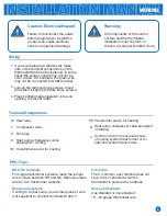
RH & RC terminals
For single transformer systems, leave the jumper
wire in place between RH and RC. Remove jumper
wire for two transformer systems.
Heat pump systems
If wiring to a heat pump, use a small piece of wire
(not supplied) to connect terminals W and Y.
C terminal
The C (common wire) terminal does not
have to be connected when the
thermostat is powered by batteries.
Wire specifications
Use shielded or non-shielded
18 - 22 gauge thermostat wire.
PRO1 Tips:
Wiring
Terminal Designations
If you are replacing a thermostat, make
note of the terminal connections on the
thermostat that is being replaced. In some
cases the wiring connections will not be
color coded. For example, the green wire
may not be connected to the
G
terminal.
Loosen the terminal block screws. Insert
wires then retighten terminal block screws.
Place nonflammable insulation into wall
opening to prevent drafts.
1.
2.
3.
Heat relay
Compressor relay
Fan relay
Heat pump changeover valve
energized in cooling
Transformer power for cooling
Transformer power for heating
Heat pump changeover valve energized
in heating
Common wire from secondary side
of cooling system transformer or for
heat only system transformer
W
Y
G
O
RC
RH
B
C


